
Data Sheet for Product

GAMMA instabus
Technical product information
June 2020
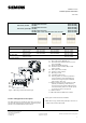
DELTA style wall switch, single
wall switch, double
wall switch, quadruple
Siemens Switzerland Ltd RS-AA
Building Technologies Division
International Headquarters
Theilerstrasse 1a © Siemens AG 2020 Update: http://www.siemens.com/gamma
CH-6300 Zug Subject to changes
7
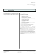
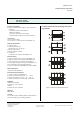
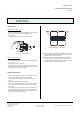
E1 Upper button(s)
E2 LED’s for status annunciation
(not available with UP 28x/2)
E3 LED for orientation lighting
E4 Lower button(s)
E5 Labeling field
E6 IR receiver (UP 287/5 only)
Installation and wiring
General description
The wall switch is slid onto the bus coupling unit (BTM)
together with its design frame (DELTA style).
Bus coupling unit (BTM) and the design frame “DELTA
style” are not included and therefore have to be ordered
separately (see current catalog).
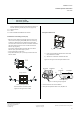
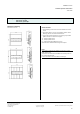
Mounting
− Slip the wall switch's main module (F5) together with
the design frame (F3) onto the bus coupling unit (BTM)
(F1) and firmly press them together.
The electrical connection between the wall switch and
the bus coupling unit (BTM) is established via a Bus
Transceiver Interface (BTI) (F2 and F4).
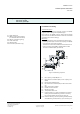
Figure 3: Mounting sequence
F1 Bus coupling unit (BTM) UP 117
F2 Bus transceiver interface (BTI) on bus coupling unit
(BTM)
F3 Design frame (DELTA style)
F4 Bus Transceiver Interface (BTI) on wall switch mod-
ule
F5 Basic push button module
F6 Holder for switch button
F7 Mounting screws
F8 Transparent label cover
F9 Learning button, for switching between normal op-
erating mode and addressing mode for receiving
the physical address (see picture 8, page 10)
F10 LED for indicating normal operating mode (LED off)
and addressing mode (LED on); upon receiving the
F13