
Data Sheet for Product

GAMMA instabus
Technical product information
June 2020
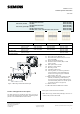
DELTA style wall switch, single
wall switch, double
wall switch, quadruple
Siemens Switzerland Ltd RS-AA
Building Technologies Division
International Headquarters
Theilerstrasse 1a © Siemens AG 2020 Update: http://www.siemens.com/gamma
CH-6300 Zug Subject to changes
2
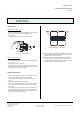
• Wall switch single, double and quadruple, with one ori-
entation LED and with one status LED per button.
• Wall switch quadruple, with one status LED per button,
scene controller, and IR receiver-decoder.
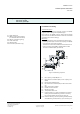
The wall switches are mounted together with the design
frame DELTA style onto a bus coupling unit (BTM). At the
same time the electrical connection between the wall
switch and the bus coupling unit (BTM) is established via
the Bus Transceiver Interface (BTI).
Bus coupling unit (BTM) and the design frame DELTA style
are not included and therefore have to be ordered sepa-
rately (see current catalog).
Common functions
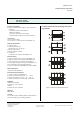
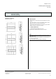
Switch buttons
Depending on the model a switch provides two to eight
switch buttons (figure 1: A1, A2, B1, B2, C1, C2, D1, D2),
which vertically function as a switch pair (A to D).
A1
A2
A1
B1
B2
A2
A1 B1 C1 D1
D2C2B2A2
Vertically aligned buttons may be used as a pair of buttons
(e.g. for defined switching/dimming, or control of shutters
and blinds, i.e. with the upper button light is turned on
and with the lower button light is turned off), or as single
buttons for sending values, single-button switching/dim-
ming or single button control of blinds.
Each individual switch button (A1, A2, B1, B2, C1, C2, D1,
D2) may be assigned one of the following functions:
• Switching (on, off, toggle)
• door bell function
• single button dimming
• single button control of solar protection (blinds, roller
shades)
• 1-bit scene control (scene 1 or 2: recall / save)
• 8-bit scene / effect control (recall, recall / save)
• Send value (8-bit value, percent)
• Send value (16-bit value, temperature value, brightness
value)
• Forced control
Depending on the selected main function another func-
tion may be executed either additionally after a time delay
(time delay configurable from 100ms to 655s) or alterna-
tively when the button is pressed for a longer period.
When switch buttons are configured as a pair then this
button pair may be assigned one of the following func-
tions:
• Dual-button dimming with stop telegram
• Dual-button control of solar protection (blinds, roller
shades)
• Send variable percent value
• Send variable 8-bit value
• 1-bit scene control (scene 1 and 2: recall / save)
• 8-bit scene / effect control (recall / save)
• Forced control
Depending on the selected main function another func-
tion may be executed additionally after a time delay (time
delay configurable from 100ms to 655s).
These options are available as additional or alternative
functions for single buttons or button pairs:
• Switching (on)
• Switching (off)
• Send percent value
• Send 8-bit value (0…255)
• Send temperature value
• Send brightness value
• Send 16-bit value (0…65535)
• 1-bit scene control (scene 1: recall / save)
• 1-bit scene control (scene 2: recall / save)
• 8-bit scene / effect control: recall
• Forced on
• Forced off
• Deactivate forced control
Orientation lighting
[not available with UP 287/5]
The orientation light (LED) of the device may be turned on
or off continuously or depending on a status object. These
configuration options are available for the orientation
light (LED):
• LED permanently off
• LED permanently on
• LED indicates IR activity (only for switch with IR receiver)
• LED indicates user operation
• LED indicates long button press
• A binary status object controls the LED for each status
value on (=1) or off (=0) respectively to either