
Data Sheet for Product

GAMMA instabus
Technical product information
February 2012
DELTA isystem wall switch single
wall switch double
wall switch triple
Technical manual UP 22x/2, UP 22x/3 and UP 22x/5, 8 pages Siemens AG
Infrastructure & Cities Sector, Building Technologies
Update: http://www.siemens.com/gamma Siemens AG 2012 Control Products and Systems
Subject to change without further notice P.O. Box 10 09 53, D93009 Regensburg
2.16.1.11/6
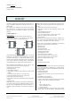
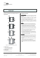
Location and function of the display and operat
ing elements
without IR receiver
with IR receiver
Figure 2: Display and operating elements
E1
Right button(s)
E2
LED’s for status annunciation
(not available with UP 22x/2)
E3
LED for orientation lighting
E4
Left button(s)
E5
Labeling field
E6
IR receiver (UP 223/5 only)
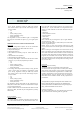
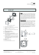
Installation and wiring
General description
The wall switch is slid onto the bus coupling unit (BTM)
(F1) together with its design frame (DELTA line / vita /
miro) (F3).
The bus coupling unit (BTM) UP 117 (F1) is already
mounted into a flushmount box (see installation instruc
tion of the bus coupling unit (BTM) UP 117).
Bus coupling unit (BTM) and the design frame “DELTA
line”, “DELTA vita”, or “DELTA miro” are not included and
therefore have to be ordered separately (see current
catalog).
Mounting
− Remove the transparent frame with the buttons (F6)
from the wall switch's main module (F5) by inserting a
screwdriver laterally into the recesses and lifting the
transparent frame upwards from the main module.
− Slip the wall switch's main module (F5) together with
the design frame (F3) onto the bus coupling unit (BTM)
(F1).
The electrical connection between the wall switch and
the bus coupling unit (BTM) is established via a Bus
Transceiver Interface (BTI) (F2 and F4).
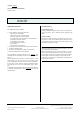
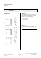
− Securely attach the wall switch's main module to the
bus coupling unit (BTM) with the screws (F7) delivered
in the package. Slip the transparent frame with the but
tons back onto the main module.
Unmounting
− Remove the transparent frame with the switch buttons
(F6) from the wall switch's main module (F5) by insert
ing a screwdriver laterally into the recesses and lifting
the transparent frame upwards from the main module
(figure 4).
− Loosen the screws (F7) securing the wall switch's main
module to the bus coupling unit (BTM) (F1).
− Remove the wall switch's main module (F5) together
with the design frame (F3) from the bus coupling unit
(BTM).