
Data Sheet for Product

GAMMA instabus
Technical product information
February 2012
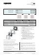
DELTA isystem wall switch, single
wall switch, double
wall switch, triple
Siemens AG UP 22x/2, UP 22x/3 and UP 22x/5, 8 pages Technical manual
Infrastructure & Cities Sector, Building Technologies
Control Products and Systems Siemens AG 2012 Update: http://www.siemens.com/gamma
P.O. Box 10 09 53, D93009 Regensburg Subject to change without further notice
2.16.1.11/5
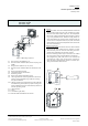
Installation notes
• The device can be used for permanent installation in
dry interior rooms and for insertion in distribution
boards or miniature housings.
V
VV
V
WARNING
• The device must be mounted and commissioned by an
authorised electrician.
• The device may be mounted in switch and socket
combinations if VDEcertified devices are used exclu
sively.
• The prevailing safety rules must be heeded.
• For planning and construction of electric installations,
the relevant guidelines, regulations and standards of
the respective country are to be considered.
Technical data
Power suply
• KNX bus voltage: via bus coupling unit (BTM) UP117
• KNX bus current: 8 mA
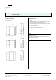
Operating elements
• 1, 2 or 3 pairs of horizontally arranged switch buttons
• Number of switching operations: > 20000 per button
• 1 learning push button:
for toggling between normal mode / addressing mode
• for reset the device to the default factory settings and
to activate manufacturer specific functions
Display elements
• 1 red LED:
for checking the bus voltage and for displaying normal
mode / addressing mode
• This LED indicated also the reset to the default factory
settings and further activated manufacturer specific
functions
• 1 LED
as orientation light in the dark
UP 22x/3 and UP 22x/5:
• 1 red LED per switch button for status annunciation
IR receiver (UP 223/5)
• Range of IR transmission: approx. 25 m under these
conditions:
with IR handheld remote S 425/72
(5WG1 4257AB72)
directed in optical direct lineofsight
up to max. 500 Lux diffuse daylight at reception lo
cation
Connections
10pin connector (BTI):
for connection to a bus coupling unit (BTM) UP 117
Physical specifications
• Housing: plastic
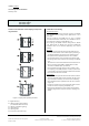
• dimensions (L x W x D):
55 x 55 x 24 mm (incl. spring)
• weight: approx. 30 g
• Fire load: approx. 740kJ
• installation:
mounted on bus coupling unit (BTM) UP 117
Electrical safety
• Degree of pollution (according to IEC 606641): 2
• Type of protection (according to EN 60529): IP 20
• Class of protection (according to IEC 61140): III
• Overvoltage category (according to IEC 606641): III
• Bus: safety extralow voltage SELV DC 24 V
• Device complies with: EN 5009022 and IEC 606641
EMC requirements
complies with EN 5009022
Environmental specifications
• climatic conditions: EN 5009022
• ambient temperature operating: 5 ... + 45 °C
• ambient temperature nonop.: 25 ... + 70 ° C
• relative humidity (noncondensing): 5 % to 93 %
Reliability
UP221/x and UP222/x
• Failure rate: 152 fit at 40°C
UP223/x
• Failure rate: 251 fit at 40°C
Markings
KNX, EIB, CE
CE mark
In accordance with the EMC guideline (residential and
functional buildings), low voltage guideline