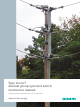
Type Vector® manual group-operated switch instruction manual Installation operation maintenance E50001-F710-A420-X-4A00 Answers for energy.
Arc flash hazard and hazardous voltages. Will cause death, serious injury or property damage. Always de-energize and ground the equipment before maintenance. Read and understand this instruction manual before using equipment. Maintenance should be performed only by qualified personnel. The use of unauthorized parts in the repair of the equipment or tampering by unqualified personnel will result in dangerous conditions which will cause death, severe injury or equipment damage.
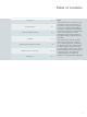
Table of contents Introduction 4-5 General description 6-7 Receiving, handling and storage 8 - 10 Installation 11 - 12 Operating handle adjustment procedure 13 Operational check out instructions 14 - 15 Maintenance 16 - 17 Note: These instructions do not purport to cover all details or variations in equipment, nor to provide for every possible contingency to be met in connection with installation, operation or maintenance.
Introduction Arc flash hazard and hazardous voltages. Will cause death, serious injury or property damage. Always de-energize and ground the equipment before maintenance. Read and understand this instruction manual before using equipment. Maintenance should be performed only by qualified personnel. The use of unauthorized parts in the repair of the equipment or tampering by unqualified personnel will result in dangerous conditions which will cause death, severe injury or equipment damage.
Introduction Signal words The signal words "danger," "warning" and "caution" used in this instruction manual indicate the degree of hazard that may be encountered by the user. These words are defined as: Danger - Indicates an imminently hazardous situation which, if not avoided, will result in death or serious injury. Warning - Indicates a potentially hazardous situation which, if not avoided, could result in death or serious injury.
General description Introduction Siemens type Vector® manual groupoperated air switch is precision built equipment designed to function efficiently under normal operating conditions. It is designed and manufactured to operate within the parameters established in ANSI/ IEEE and NEMA standards for disconnecting and load-interrupter switches. Performance requirements of these standards have been met or exceeded by these designs. Specific standards which apply include: ANSI/IEEE C37.
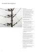
General description Scope These instructions cover the installation, operation and maintenance of a Siemens type Vector® manual group-operated air switch. The equipment designs described in this instruction manual consists of group-operated air switch for application up to 38.0 kV. A typical type Vector manual group-operated air switch is shown in Figure 1. All diagrams, descriptions and instructions apply to all of the above classes and designs unless noted otherwise.
Receiving, handling and storage Receiving Pipe guide assembly Each type Vector® manual group-operated air switch is securely blocked and braced for shipment on a pallet. It is crated, boxed or covered as required by shipping conditions. If special handling is required, it is so indicated. The type Vector manual group-operated air switch must be handled carefully when unloading.
Receiving, handling and storage 3. A ny visible damage must be noted on the delivery receipt and acknowledged with the driver’s signature. The damage should be detailed as much as possible. It is essential that a notation "possible internal damage, subject to inspection" be included on delivery receipt. If the driver will not sign the delivery receipt with damage noted, the shipment should not be signed for by the consignee or their agent. 4.
Receiving, handling and storage Lifting and moving There are a number of methods that can be used in handling the type Vector® manual group-operated switch that, when properly employed, will not damage the type Vector manual group-operated switch. The handling method used will be determined by conditions and available equipment at the installation site. The lifting method used in handling the type Vector manual group-operated switch is achieved via the single point hoist bracket.
Installation Installation Installation instructions for the type Vector manual group-operated air switch are detailed in the following steps: A 1. Drill two mounting holes 11/16" in diameter located per the user's construction standards and spaced per Siemens assembly drawing. 2. Install the mounting bolts in the holes. Mounting bolts to be furnished by others. 3. Using the single-point lift bracket, lift the air switch approximately 4' (1.
Installation A EN A Item Description A Loosen bolt A CL O SE D OP A Figure 5: Loosen bolts 8. Remove single-point lift bracket. 9. G round the air switch unit (and surge arresters if required) using #2 or larger copper wire. A grounding point (1/2-13 tapped hole) is provided in the side of the mounting bracket (refer to assembly drawing provided). 10.
Operating handle adjustment procedure Operating handle adjustment procedure The next series of steps address adjusting the position of the handle assembly and lock segment assembly so that the handle can be inserted into the OPEN and CLOSED slot correctly. Important: It is extremely important to adjust the handle position so it is impossible to place the operating handle in the CLOSED slot unless the air switch blades are fully closed.
Operational check out instructions Operational check out instructions A C D C D B Item Description A Spacer B Blade C Contacts D Auxiliary contacts Figure 10: Blade A Item Description A Air gap 1/8" (3.2 mm) Operational check out instructions for the type Vector® manual group-operated switch are detailed in the following steps: 1. S witches are fully adjusted and inspected before they leave the factory. There should be no need to adjust the switch unit. 2.
Operational check out instructions 2. As the blade continues to rotate open, the interrupter lever must make full metal-to-metal contact with the contactor (refer to Figure 13: Contactor connection). At this point, the load then transfers from the auxiliary contacts to the interrupter's lever arm so that the interrupter now carries the full load. 3. As the blade continues to rotate open, the interrupter will trip thus interrupting the load.
Maintenance Maintenance Maintenance instructions for the type Vector® manual group-operated switch are detailed in the following steps: 1. P eriodically operate the switch and check for actions described in Operational check out instructions on pages 14-15. Lubricate the jaw, auxiliary contacts and the end of the blade with Dow Corning® Molykote FS1292 white grease. 2.
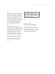
Maintenance Table 2: Remarks 17
Published by and copyright © 2011: Siemens AG Energy Sector Freyeslebenstrasse 1 91058 Erlangen, Germany Siemens Energy, Inc. 99 Bolton Sullivan Drive Heber Springs, AR 72543 For more information, contact +1 (800) 347-6659 +1 (501) 362-8296 Order No. E50001-F710-A420-X-4A00 Replaces No. VEC4100 10/2/08 Printed in USA All rights reserved. Trademarks mentioned in this document are the property of Siemens AG, its affiliates, or their respective owners. Subject to change without prior notice.