
Instruction manual


SITRANS TW
A5E00054075-05
97
Hardware functions
3.7.4 Software parameterization
The following order must be observed for the parameterization of the plug:
1. HART-Communicator
− Selection sensor class = mV transmitter
− Selection sensor type = -120 to 1000 mV
− Input of following special characteristic pairs:
− Selection type of linearization = special characteristic
2. SIMATIC PDM
− Selection sensor class = mV transmitter
− Selection sensor type:
− The corresponding special characteristic pairs and the type of linearization are
set automatically by SIMATIC PDM.
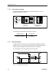
3. If the U/I input plug is o be used in connection with another (“customer-specific”)
special characteristic, the voltage divider R1, R2 or the current shunt R3 of the
U/I input plug must be taken into account in the characteristic input (see circuit
diagram figure 10).
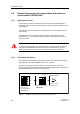
4. In voltage measurement (measuring range –1.2 to 10 V), all input signals X
i
must
be multiplied with the voltage divider:
The characteristic input values X
SKL,i
must be specified in the unit mV.
Example: (V-signal corresponds to the physical oxygen content [%O2])
(X
SKL,1
= X
1
xR
T
= 1 V x 0.09124087 = 0.09124087 V = 91.2409 mV)
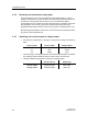
Measuring range Value pairs
-1.2 to 10 V X1 = -109.4891 mV Y1 = -1.2000 V
X2 = 912. 4088 mV Y2 = 10.0000 V
-12 to 100 mA X1 = -120 mV Y1 = -12 mA
X2 = 1000 mV Y2 = 100 mA
Measuring range Sensor type
-1.2 to 10 V
-12 to 100 mA
-1.2 to 10 V (with U/I plug (7NG3092-8AW)
-12 to 100 mA (with U/I plug 7NG3092-8AW)
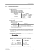
Sensor signal
X
i
-> X
SKL,i
(input values)
Linearized signal
Y
SKL,i
(input values)
X
1
: 1 V -> X
SKL,1
: 91.2409 mV
X
2
: 7 V -> X
SKL,2
: 638.6861 mV
X
n
: 8 V -> X
SKL,n
: 729.9270 mV
The input values X
SKL,i
must be entered in the
unit mV.
Y
SKL,1
:3**
Y
SKL,2
:21**
Y
SKL,n
:35**
** corresponds to [%O2]
R
T
=
R2
R1+R2
=
100 kW
996 kW + 100 kW
= 0,09124087