
Instruction manual


SITRANS TW
96 A5E00054075-05
Hardware functions
3.7.2 Connection and wiring
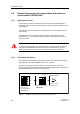
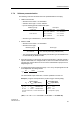
The U/I input plug must be mounted on the input plug (terminal 1-4) of the
SITRANS TW as shown in figure 9.
Figure 9 Connection of U/I input plug to SITRANS TW
The hardware parameterization must be done as follows:
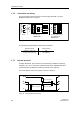
3.7.3 Internal structure
A voltage divider (R1, R2) is used in the U/I input plug to adapt the measuring
voltages (-1.2 to 10 V) to the input measuring range of the SITRANS TW and a
current shunt (R3) to adapt the measuring currents (-12 to 100 mA).
The circuit diagram of the U/I input plug is shown in figure 10.
Figure 10 Circuit diagram U/I input plug
Measuring range Jumper position
Voltage (-1.2 to 10 V)
current (-12 to 100 mA)
A-B
B-C (default)
-12..100mA -1,2..10V
4
3
2
1
4
3
2
1
U+
U-
I+
I-
A
B
C
Sensor U/I input plug Input plug (terminal 1-4)
7NG3092-8AV from SITRANS TW
7NG3242-0***0
U+
U-
I+
I-
R3
10R / 0.1%, 15ppm
R2
100k / 0.1%, 15ppm
4
3
2
1
R1
996k / 0.1%, 25ppm
A
B
C