
Instruction manual


SITRANS TW
90 A5E00054075-05
Hardware functions
3.3 Sensor error / limit value alarm
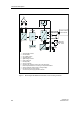
The sensor error / limit value alarm can be parameterized as follows (pin assignment
of the relay output, see figure 19, page 127).
• Idle current principle
− Device switched off : Terminals 10 and 11 connected
− Device switched on and no error : Terminals 9 and 11 connected
− Device switched on and error : Terminals 10 and 11 connected
• Open circuit principle:
− Device switched off : Terminals 10 and 11 connected
− Device switched on and no error : Terminals 10 and 11 connected
− Device switched on and error : Terminals 9 and 11 connected
3.4 Connection HART communication
• The HART modem or HART Communicator should be conn ected as follows
depending on the type of analog output (current or voltage output) (see figure 19
for pin assignment of the analog output / HART connection).
• If the analog output is in the current output 0 ... 20 mA mode or current output
0 ... 10V mode, the test jack (6, figure 2, page 83) must be bridged at 0 mA or at
0V for correct HART communication. A suitable short-circuit connector can be
ordered as an accessory as follows:
− Add the suffix S01 to the order number of the SITRANS TW or
− order as accessory with order number 7NG3092-8AP
Communication with HART
modem / HART communicator
Current
output
Voltage
output
HART connection at terminal 5 and 6
→ R
load
for HART modem
→ R
load
for HART Communicator
available
230 ... 500Ω
230 ... 650Ω
not available
HART connection at terminal 7 and 8
→ R
load
for HART modem
→ R
load
for HART Communicator
available
none
1) 2)
none
1) 2)
available
none
1)
none
1)
1)
No load may be connected between terminals 7 and 8.
2)
A load (max. 650Ω) must be connected between the terminals 5 and 6.