
Instruction manual


SITRANS TW
A5E00054075-05
89
Hardware functions
3 Hardware functions
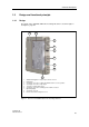
3.1 Operating display
The green operating indicator (5, figure 2, page 83) signals the following
operatingstates:
If several errors occur simultaneously, flashing follows the given order of priority
(priority 1 = highest priority)
3.2 Test jack for output signal
• The test socket (6, figure 2, page 83) is used to check the 0/4 ... 20 mA current
with a measuring instrument at current output. The connection is made by 2 mm
test jack plugs. The voltage drop at the ammeter may not exceed 0.3V at 23 mA
output current.
• The test jack has no function for voltage output.
• If the analog output is in the current output 0 ... 20 mA mode or current output
0 ... 10V mode, the test jack must be bridged at 0 mA or at 0V for correct HART
communication. A suitable short-circuit connector can be ordered as an acces-
sory as follows:
− Add the suffix S01 to the order number of the SITRANS TW or
− order as accessory with order number 7NG3092-8AP
• no power supply : operating indicator does not light
• faultless operation
: operating indicator lights
• faulty operation : operating indicator flashes
− Diagnostic alarm:
→ sensor error : flashing frequency = 1Hz (priority 1)
→ hardware- / firmware error : flashing frequency = 1Hz (priority 1)
− Diagnostic warning
→ limit value exceeded /
dropped below : flashing frequency = 5Hz (priority 2)
→ output saturation warning : flashing frequency = 1Hz (priority 3)
→ measured value outside
sensor limits : flashing frequency = 1Hz (priority 4)