
Instruction manual


SITRANS TW
138 A5E00054075-05
Ordering data
Temperature Measurement
Transmitters for rail mounting
SITRANS TW
four-wire system, universal, HART
■
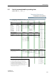
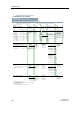
List of parameterizable operating data (Order codes F
7
7
... K
7
7
)
Operating data according to default setting Order No. with Order code: 7NG3242 -
7
7
7
7
7
-Z Y01
Order codes: F
7
7
... K
7
7
7 7 7
+
7 7 7
+
7 7 7
+
7 7 7
+
7 7 7
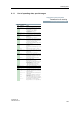
Sensor
Thermocouple elements Volt age
measure-
ment
Filter
time
1)
Output sig-
nal and line
filter
2)
Failure signal Limit
monitor
3)
Type Temperature range
B: Pt30 %Rh/ 0 ... 1820 °C A 0 0 Temperature-
linear
F 0 0 0 s G 0 0 4 ... 20 mA/
2...10V
with line filter:
with line break-
age/fault:
Limit monitor-
ing ineffective
(but sensor
fault signalling
with closed-
circuit opera-
tion)
K 0 0
C:W5 %Re 0 ... 2300 °C
A 0 1 0.1 s G 0 1
D:W3 %Re 0 ... 2300 °C A 0 2 Voltage-
linear
F 1 0 0.2 s G 0 2
E:NiCr/CuNi -200 ... +1000 °C A 0 3 0.5 s G 0 3 50 Hz H 0 0 to full scale J 0 0
J:Fe/CuNi (IEC) -210 ... +1200 °C
A 0 4 1 s G 0 4 60 Hz H 0 1 to start of scale J 0 1
K:NiCr/Ni -200 ... +1372 °C
A 0 5 2 s G 0 5 10 Hz
4)
H 0 2 hold last value J 0 2
L: Fe/CuNi (DIN) -200 ... +900 °C A 0 6 5 s G 0 6 0 ... 20 mA/
0...10V
with line filter:
N:NiCrSi/NiSi -200 ... +1300 °C A 0 7 10 s G 0 7 no monitoring J 0 3
R:Pt13 %Rh/Pt -50 ... +1760 °C A 0 8 20 s G 0 8 Effective
5)
Y 7 0
S:Pt10 %Rh/Pt -50 ... +1760 °C
A 0 9 50 s G 0 9 50 Hz H 1 0 Safety value
5)
Y 6 0
T:Cu/CuNi (IEC) -200 ... +400 °C A 1 0 100 s G 1 0 60 Hz H 1 1
U:Cu/CuNi (DIN) -200 ... +600 °C A 1 1 Special
time
5)
Y 5 0 10 Hz H 1 2
Resistance thermometer
(max. permissible line resistances see
„Technical specifications“)
Vol tage
measure-
ment
Filter
time
1)
same as for
thermocou-
ple ele-
ments
Output sig-
nal and line
filter
2)
same as for
thermocou-
ple elements
Failure signal
Limit
monitor
3)
same as for
thermocouple
elements
Pt100 (DIN IEC) -200 ... +850 °C A 2 0 Temperature-
linear
F 0 0 with line break-
age/fault:
Pt100 (JIS) -200 ... +649 °C A 2 1
Ni100 (DIN) -60 ... +250 °C A 2 2 Resistance-
linear
F 2 0 to full scale J 0 0
to start of scale J 0 1
hold last value J 0 2
no monitoring J 0 3
Safety value
5)
Y 6 0
with line break-
age or short-cir-
cuit/fault:
to full scale J 1 0
to start of scale J 1 1
hold last value J 1 2
no monitoring J 1 3
Safety value
5)
Y 6 1
Resistance-based sensors, potenti-
ometers
Vol tage
measure-
ment
Filter
time
1)
same as for
thermocou-
ple ele-
ments
Output sig-
nal and line
filter
2)
same as for
thermocou-
ple elements
Failure signal
Limit
monitor
3)
same as for
thermocouple
elements
(max. permissible line resistances see
„Technical specifications“)
A 3 0 Resistance-
linear
F 2 0 with line break-
age/fault:
to full scale J 0 0
to start of scale J 0 1
hold last value J 0 2
no monitoring J 0 3
Safety value
5)
Y 6 0
mV, V and A, mA sources
A 4 0 Vol tage
measure-
ment
Filter
time
1)
same as for
thermocou-
ple ele-
ments
Output sig-
nal and line
filter
2)
same as for
thermocou-
ple elements
Limit
monitor
3)
same as for
thermocouple
elements
Source pro-
portional
F 3 0
1)
Software filter to smooth the result
2)
Filter to suppress line disturbances on the measured signal.
3)
If signalling relay present
4)
for special appliciations
5)
Operating data: see „Special operating data“