
Instruction manual


SITRANS TW
A5E00054075-05
131
Installation and commissioning
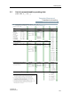
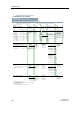
Table 7 Sensor interfaces
6.5 Commissioning
The software operating data of the transmitter must be set to meet the requirements
of the current measuring job and must correspond to specifications on the software
rating plate. If the software operating data do not match the data on the software
rating plate, the rating plate must be corrected or replaced by a new one (Chapter
3.5.2, page 92).
The hardware operating data must also match the data on the hardware rating plate.
If changes are made to the hardware parameterization (switching over from current
to voltage or vice versa), the current state on the hardware rating plate must be
documented (see Chapter 3.5.3, page 92).
Sensor interfaces for devices with order number: 7NG3242-xxxx0
Resistance thermometer, resistance transmitter, potentiometer
1
2
3
4
Two-wire circuit Resistance for line compensation is parameterizable
Three-wire circuit
Four-wire circuit
Difference/average value circuit: 2 resistors parameterizable for line
compensation
Thermocouples
5
6
7
Determining the comparative temperature with built-in Pt100 or with fixed
reference temperature
Determining the comparative temperature with external Pt100, resistance for
line compensation is programmable
Difference / average circuit with internal comparative temperature
mV transmitter
8 Two-wire circuit
with accessories
9 Determining the reference temperature with reference point terminal
7NG3092-8AV
10 Voltage measurement -1.2 to 10 V with U/I input plug 7NG3092-8AV
11 Current measurement -12 to 100 mA with U/I input plug 7NG3092-8AV
Sensor input wirings for devices with order number: 7NG3242-xxxx[1-3]
V transmitter
12 Two-wire circuit
Sensor input wirings for devices with order number: 7NG3242-xxxx[4-8]
µA- / mA transmitter
13 Two-wire circuit