
Instruction manual


SITRANS TW
A5E00054075-05
129
Installation and commissioning
6.4 Sensor input wiring
6.4.1 General
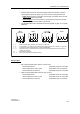
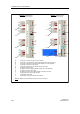
The following information refers to Chapter 6.4.2, page 130.
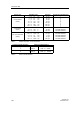
• Measuring channel 1: Measuring variable between terminals 2 and 3 on the
input plug
• Measuring channel 2: Measuring variable between the terminals
→ 3 and 4 on the input plug in connection no. 4
→ 1 and 4 on the input plug in connection nos. 6 and 7
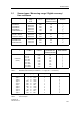
• In difference and average circuits, the measured value calculation is determined
by the type of measurement. Otherwise the measured value is determined by
measuring channel 1. The following coding is used for the type of measurement.
• The short-circuit bridges drawn in the connections must be inserted on site on
the systemside.
WARNING
In devices with “intrinsically safe” type of protection, make sure the blue cable
housing delivered ex-factory is firmly mounted on the input plug before
commissioning the devices.
NOTE
It applies generally for laying connecting cables and signals names for EMC
reasons:
- Lay signal cables separately from cables with voltages of > 60V
- Use cables with twisted wires
- Avoid the vicinity of large electrical installations or use screened cables
Measuring type Measured value calculation
single-channel
difference circuit 1
difference circuit 2
average value
Measuring channel 1
measuring channel 2 – measuring channel 1
measuring channel 2 – measuring channel 1
½ x (measuring channel 1 + measuring channel 2)