
Instruction manual


SITRANS TW
128 A5E00054075-05
Installation and commissioning
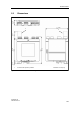
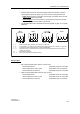
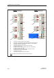
Figure 20 Coding of the screw-type connectors
Example: 7NG3242-0Bxxx
(U
H
= 24V, non-Ex device)
A1 screw-type connector for input in non-Ex devices
A2 screw-type connector (blue) in cable housing (blue) for input in Ex devices
B screw-type connector for output and HART modem for on-site operation.
C screw-type connector for relay output
D screw-type connector for power supply and PE connection
E pin strip in device for input
F pin strip in device for output and HART modem for on-site operation.
G pin strip in device for relay output
H pin strip in device for power supply and PE conductor connection
J coding profile in the screw-type connector
K coding tab in the pin strip
L blue marking of the Ex connection in Ex devices
Note:
pin assignment of individual screw-type connectors, see fig. 16
Example:
7NG3242-1Axxx
(UH = 230V, Ex device)
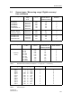
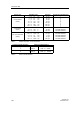
Rating plate text on front of device
Rating plate text on front of device