
Instruction manual


SITRANS TW
A5E00054075-05
127
Installation and commissioning
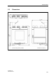
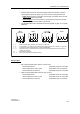
• All screw-type connectors are mechanically coded at the factory to prevent
confusing them (figure 20, page 128). The connector coding also ensures:
− Input circuit: Incorrect connection of screw-type connectors for Ex circuits
and non-Ex circuits is prevented.
− Power supply: Incorrect connection of screw-type connectors to a power
supply not suitable for the device is prevented.
• The specified data for the electrical connection (Chapter 5, page 117) must be
observed.
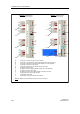
Figure 19 Wiring diagram input, outputs, power supply
Relay output:
• Idle current principle (relay opens in case of error)
− Device switched off : Terminals 10 and 11 connected
− Device switched on and no error : Terminals 9 and 11 connected
− Device switched on and error : Terminals 10 and 11 connected
• Open circuit principle (relay closes in case of error)
− Device switched off : Terminals 10 and 11 connected
− Device switched on and no error : Terminals 10 and 11 connected
− Device switched on and error : Terminals 9 and 11 connected
Mains
connection
GWM Sensor
Relay output
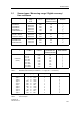
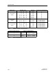
1 - 4 : Measuring input (wiring variations, see Chapter 6.4, page 129)
5 - 6 : Analog output (U or I output can be parameterized by plug-in jumpers, see Chapter 3.5.3, page 92)
7 - 8 : Connection of HART communication for on-site parameterization
9 - 11 : Output sensor error / limit value alarm as a relay contact (parameterization behavior see below or
Chapter 3.3, page 90)
12 : PE conductor connection
13 - 14 : Input power supply (reverse polarity protected)