
Instruction manual


SITRANS TW
A5E00054075-05
109
Functions / Operation by HART
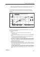
• Diagnostic alarm: The device goes into the alarm current / alarm voltage state.
The diagnostic event is provided additionally via HART. The output via the
message relay is parameterizable.
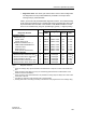
Table 1 gives a list of all parameterizable diagnostic functions. The standard setting
for all warnings and alarms is off. The diagnostic warning and diagnostic alarm must
be parameterized with the HART communicator or with SIMATIC PDM. If several
errors occur simultaneously, the given priorities apply (priority 1 = highest priority)
Table 1 Diagnostic functions
1)
Output to message relay optional activation and deactivation of output in the Limit value mode menu
item
2)
Output to analog output Output can only be controlled by global activation and deactivation of the
break and short-circuit detection
3)
Output to analog output Parameterization not possible, the analog output is always set to alarm value
in the event of an error
4)
Time delay for response of the message relay is programmable
5)
Flashing starts with a time delay (time delay is the same as was programmed for the message relay)
Diagnostic function Priority
Output of diagnostic function via
HART
Analogoutput Message
relay
4)
LED
Diagnostic alarm:
Sensor error
1) 2)
Sensor break
Sensor short-circuit
Hardware / firmware error
1) 3)
RAM / ROM / EEPROM error
Checksum error
Electronic error
Enter special characteristic!
1
1
1
1
1
1
Status
Status
Status
Status
Status
Status
to alarm value
to alarm value
to alarm value
to alarm value
to alarm value
to alarm value
yes
yes
yes
yes
yes
no
f = 1Hz
f = 1Hz
f = 1Hz
f = 1Hz
f = 1Hz
f = 1Hz
Diagnostic warning
Measured value below lower limit
1)
Measured value above upper limit
1)
Output saturation warning
1)
Measured value below sensor limit
Measured value above sensor limit
2
2
3
4
4
Status
Status
Status
Status
Status
unchanged
unchanged
unchanged
unchanged
unchanged
yes
yes
yes
no
no
f = 5Hz
5)
f = 5Hz
5)
f = 1Hz
5)
f = 1Hz
f = 1Hz