
User's Manual


TC12 Installation, Commissioning & Maintenance Handbook
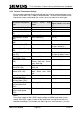
Figure 26 - Outstation Output Connections
OUTSTATION PROCESSOR PCB - PL4
34-way connector to Relay Outputs.
PIN NAME
1
2
Output 1
3
4
Output 2
5
6
Output 3
7
8
Output 4
9 Output 5
10
11
12
Output 6
13 Output 7
14
15
16
Output 8
17
18
Output 9
19
20
Output 10
21 Output 11
22
23
24
Output 12
25 Output 13
26
27
28
Output 14
29
30
Output 15
31
32
Output 16
33
34
Transmit Confirm Relay Output
3.2.3 of SCOOT Detector Inputs to Free-Standing TC12 OTU
n a free-standing TC12 OTU, the SCOOT detector inputs to the OTU should be
connected to the normally closed contacts on the detector backplane. On an STC
detector back plane these are the odd numbered pins starting at pin 9.
.6 Connection
O
666/HE/43100/000 Page 74 Issue 9