
User's Manual


TC12 Installation, Commissioning & Maintenance Handbook
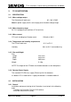
Figure 18 - OUTSTATION PCB LAYOUT
1 (TOP)
1 (TOP)
PL2
40 Way for 32
buffered
inputs
34
Transmit
Confirm
output
Serial Number
LP7 +5V LED
PL4
34 Way
for 16 Relay
outputs &
40
Line Jack Sockets
Var ian t No
PL3
14-Way
connector
to PSU
1
14
FS2
Fuse for
Buffered
inputs,
+24V
Lithium Battery
ON / OFF
SK
PL1
to LMU inputs
3
SK4
600R / HI-Z Selector
1
50
6-Way Telecom Socket
50-Way
connector
S3
S4
2/4 Wire
Selector
S6
B1
Battery
S2
SK2
Line Level
Firmw
PRO
S
2
K 1
5 Way Connector
to Handset
5
terminal
LP2
LP3
P4
St at us
LEDs
L
LP
are
M
Fig
ure 19 - OUTSTATION PCB and DAUGHTER BOARD LAYOUT
1 (TOP)
1 (TOP)
PL2
40 Way for 32
buffered
inputs
34
PL4
34 Way
for 16 Relay
outputs &
Transmit
Confirm
output
40
Serial Number
LP7 +5V LED
Line Jack Sockets
Varian t No
PL3
14-Way
connector
to PSU
1
14
FS2
Fuse for
Buffered
inputs,
+24V
Lithium Battery
ON / OFF
S 3
PL1
50-Way
connector
to LMU inputs
1
K
SK4
600R / HI-Z Selector
50
6-Way Telecom Socket
S3
S4
2/4 Wire
Selector
S6
B1
Battery
Daught er
Board
S2
SK 2
Line Level
Firmware
PROM
666/HE/43100/000 Page 64 Issue 9