
User's Manual


TC12 Installation, Commissioning & Maintenance Handbook
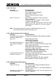
Figure 17 - Master Switch Panel Fuses
FS6
FS7
PSU
FS1 FS2 FS3 FS4 FS5
MASTER SW
10A
WAL L
MAP
CABINET
RCD
5A
FRONT
13A SKT
5A
REAR
13A SKT
5A
MAINS
SKT B
5A
MAINS
SKT C
5A
MAINS
SKT D
5A
MAINS
SKT E
Master Switch and RCD.
The diagram above shows the layout of the fuses on the Master Switch Panel
uses FS1 to FS7 is shown along with the fuse value.
.
ap power supply, if fitted.
2.4.1
hould be replaced every five years, otherwise it may
o the equipment. The replacement date is therefore five years
wer Supply Tests
of being faulty, check the voltage outputs of the
s easier.
terminal pins on the PCB. The terminal
also labelled with a voltage. Check these
e between TP7, GND and TP5, +5 V should be between 4.75 V and
.25 V.
assembly. The position of the f
Fuse FS1 protects the front Mains sockets.
Fuse FS2 protects the rear Mains sockets
Fuses FS3 to FS6 protect the Mains supply to up to four 19” racks.
Fuse FS7 protects the Wall M
0 PSU
The part number of the power supply fitted to the PSU board is 667/7/22631/000.
The Instation power supply s
become prone to overheating. There may be a label already on the PSU showing
the date it was shipped. This should be covered with a label showing the date the
PSU is fitted int
after the date on the label.
Po
f the power supply is suspectedI
power supply using a Multimeter.
Slide the PSU Board forward slightly to make acces
Wires connect from the power supply to
pins are labelled TP4 to TP9 and each is
as follows:
The voltag
5
666/HE/43100/000 Page 60 Issue 9