
User's Manual


TC12 Installation, Commissioning & Maintenance Handbook
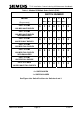
Figure 11 - Transformer PCB Layout
1 (TOP)
37
1 (TOP)
14
PL2
14 Way to
Modem PCB
S
PL1
1
37 Way ‘D’
to MDF.
1 (TOP)
37
S2
S3
S4
PL3
37 Way ‘D’
to MDF.
Variant
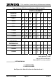
Figure 12 - ITU 19" Rack (Rear View)
PSU
ITU Rack 6U ,
System
Modem Output
14 Way connector
to PSU
24 Way connector
to PC
IDC connectors
with IDC cable:
14way to 37 Way
PSU
Telephone lin
37 way ‘D’
.
e I/F
666/HE/43100/000 Page 35 Issue 9