
User's Manual


TC12 Installation, Commissioning & Maintenance Handbook
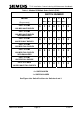
Table 2 - M , 6 and 7)
SWITCH NUMBER
odem PCB Line Level Switches (SW2, 3
OUTPUT 1 2 3 4 5 6 7 8
POWER
0dBm
1 0 0 0 - - 1 1
-3dBm
1 0 0 1 - - 1 1
-6dBm
0 1 0 0 - - 1 1
-9dBm
0 1 0 1 - - 1 1
-10dBm
0 0 1 0 - - 1 1
-13dBm
0 0 0 0 - - 1 1
-16dBm
0 0 0 1 - - 1 1
RECEIVE
THRESHOLD
-42dBm
- - - - 0 0 1 1
-39dBm
- - - - 0 1 1 1
-33dBm
- - - - 1 0 1 1
↑ ↑
Switch positions 7 and 8
apply to SW2 and SW3 only.
SW6 and SW7 are 6-way switches
.
SETTING FOR UK
0 = SWITCH OPEN
1 = SWITCH CLOSED
See Figure 8 for Switch Positions for Switches 0 and 1
666/HE/43100/000 Page 32 Issue 9