
User's Manual


TC12 Installation, Commissioning & Maintenance Handbook
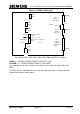
Figure 10 - Modem PCB Layout
1 (TOP)
24
PL1
24 Way to
IMD panel
1 (TOP)
14
PL2
14 Way to
PSU card
S1
PL3
ay ‘D’
PCB.
37
S2
37 W
to MDF or
Transformer
1 (TOP)
S3
S4
S5
S6
S7
Mode
Select
0 1
Line
Level
Line
Level
2/4 Wire
Selector
Level
4 Wire
Level
2 Wire
Level
Transformer
Select
Off PCB ‘0’
Level
On PCB ‘1’
Level
Line
Level
Line
Level
0 1
Variant
is:
OPEN i.e. ‘0’ WHEN
CLO
As a
SW7
For SW4, 4-wire is selected with the switch to the left and 2-wire is selected with the
switch to the right as shown above.
For switches SW1, SW2, SW3, SW3, SW5, SW6 and SW7 the switch
PUSHED DOWN TO THE LEFT, and
SED i.e. ‘1’ WHEN PUSHED DOWN TO THE RIGHT
reminder the ‘0’ and ‘1’ positions are shown on the silkscreen below SW1 and
.
666/HE/43100/000 Page 30 Issue 9