
User's Manual


TC12 Installation, Commissioning & Maintenance Handbook
retaining screws line up with large holes in the slots for the screws. The power
supply can be taken off by moving it sideways.
Power Supply Tests
If the power supply is suspected as being faulty, check the output voltage of the
power supply on the Outstation.
Make sure the Outstation is powered down.
Disconnect the 13-way connector from the end of the power supply.
Power up the Outstation.
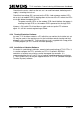
Check the +5 V output is between 4.75 V and 5.25 V (see Figure 31 for details of
where to connect Multimeter).
Check the +24 V output is between 22.8 V and 25.2 V (see Figure 31 for details of
where to connect Multimeter).
Power down the Outstation.
Re-connect the 13-way connector to the power supply.
Figure 31 - Outstation PSU Voltage Checks
L N E
13 1
CONNECTIONS
1,2 & 3 5V } 5V
4,5 & 6 0V }Supply
7 0V } 24V
13 24V} Supply
10 Power Fail Signal
8,9,11 & 12 Not connected
This diagram shows the end view of the Outstation Power Supply
(Computer Products NFS110-7602PK)
Mains
connector
Connectors shown
without mating halves,
to show pins.
PSU Case
666/HE/43100/000 Page 134 Issue 9