
User's Manual


TC12 Installation, Commissioning & Maintenance Handbook
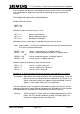
In this example, the pelican is monitored with three current sensors (see example
4 for combined wait, pedestrian and vehicle monitoring using a single current
sensor).
The configuration commands are detailed below.
Enable LMU write access:
AMB = 35
NEC = 249
Allocate function of current sensors 1 to 3:
KPT 1 = 2 :pelican vehicle phase
KPT 2 = 4 :pelican pedestrian phase
KPT 3 = 6 :60 Watt wait indicators
Allocate the mains state inputs associated with each current sensor:
Note: Input numbers 1 to 32 on the buffered input connector are referenced as 0
to 31 on the handset commands.
KMS 0 1 = 31 :sensor 1 vehicle green is on digital input 32
KMS 1 1 = 29 :sensor 1 opposing pedestrian green is on digital input
30
KMS 0 2 = 30 :sensor 2 pedestrian green is on digital input 31
KMS 0 3 = 29 :sensor 3 wait is on digital input 30
Allocate aspect drive identity to each current sensor:
KAD 1 = 0 :sensor 1, vehicle is phase A
KAD 2 = 1 :sensor 2, pedestrian is phase B
KAD 3 = 1 :sensor 3, wait is phase B
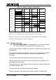
Example 6 - 8 phase controller with phase overlaps, non fixed phases in stages
Description: Eight phase intersection controller with no lamp dimming. Six of the
phases (A to F) are vehicle and one is pedestrian (H), Phase G is a
Green arrow phase which only appears when demanded. Phase D
appears in two stages which may run sequentially.
The wait indicators in this example are monitored using their own current sensors,
separately from those used to monitor the pedestrian red and green (see example
3 for combined wait and pedestrian monitoring on one current sensor).
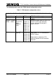
General: Refer to Figure 27, which shows the relationship between the OTU
inputs, the OTU software modules and the OTU Reply bytes. For
the phase to stage allocation see Figure 29.
666/HE/43100/000 Page 122 Issue 9