
User's Manual


TC12 Installation, Commissioning & Maintenance Handbook
normal direction loop connects (the reverse direction loop is
.
onding to
ver the handset
ts.
ommands CUD and UDT. Note: These functions only work if they are enabled in
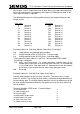
3.3.3.13 Reply bit function (GRL)
omm nt: or ea bit in this reply byte.
ch reply
byte. The {function} field defines the source that sets the bit, or in
the case of SCOOT loops a group of four bits.
The various functions are as follows:
0 = For GRL command, this indicates that the reply bit is driven directly.
For GOL command, this indicates that the output bit is driven directly
from the corresponding UTC control bit.
1 = Red Lamp Monitor group 0 - first red fail (RL1)
2 = Red Lamp Monitor group 0 - second red fail (RL2)
3 = Red Lamp Monitor group 0 - any lamp fail (LF)
4 = Red Lamp Monitor group 1 - first red fail
5 = Red Lamp Monitor group 1 - second red fail
6 = Red Lamp Monitor group 1 - any lamp fail
7 = Red Lamp Monitor group 2 - first red fail
8 = Red Lamp Monitor group 2 - second red fail
9 = Red Lamp Monitor group 2 - any lamp fail
10 = Red Lamp Monitor group 3 - first red fail
11 = Red Lamp Monitor group 3 - second red fail
12 = Red Lamp Monitor group 3 - any lamp fail
33 = Red Lamp Monitor group 4 - first red fail
34 = Red Lamp Monitor group 4 - second red fail
35 = Red Lamp Monitor group 4 - any lamp fail
36 = Red Lamp Monitor group 5 - first red fail
37 = Red Lamp Monitor group 5 - second red fail
38 = Red Lamp Monitor group 5 - any lamp fail
39 = Red Lamp Monitor group 6 - first red fail
40 = Red Lamp Monitor group 6 - second red fail
41 = Red Lamp Monitor group 6 - any lamp fail
42 = Red Lamp Monitor group 7 - first red fail
43 = Red Lamp Monitor group 7 - second red fail
44 = Red Lamp Monitor group 7 - any lamp fail
connected to the next input after the normal direction loop)
Note. The 32 inputs are numbered 1 to 32 in section 3.2.3.5, corresp
the associated pin on the 40 way input connector, howe
command numbers the inputs from 0 to 31, for the 32 inpu
The controller provides U/D for an Integral OTU. See the Controller Handset
C
the T400’s configuration.
GRL{Reply byte no.: 0 to 13} {bit no.: 0 to 7}={function: 0 to 255} (0)
C e F ch reply byte set up the function of each
This command is therefore repeated up to eight times for ea
666/HE/43100/000 Page 91 Issue 9