
User's Manual

Configuration of MPC with Slave Controller
16
MPC Level
V 1.0, Beitrags-ID: 42200753
Copyright Siemens AG 2010 All rights reserved
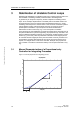
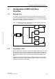
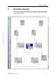
Figure 4-2 Signal flow chart of MPC with subordinated stabilizing PID controller for the
integral main transfer function g22
The slave controller stabilizes the control variable CV1 in general. The integral ef-
fect of the main transfer function g22 is compensates as well as the integral effect
of the coupling transfer function g21. The influence of MV2 on CV1 is also modified
by the slave controller due to g12.
All general notes on the configuration and commissioning of cascade controls are
relevant for this case (see Figure 5-1):
To get a correct anti windu
p calculation of the master controller, the range of
the manipulated variables of the master controller (respectively the corre-
sponding MPC channel) must be equal to the range of the external set point of
the slave controller (PID.SP_ExtHiLim… SP_ExtLoLim). Typically the MV limits
for automatic mode MViHiLim…MViLoLim are set tighter than the ones for
manual mode MViManHiLim…MViManLoLim in an MPC. Hence, the limits for
manual mode are set equal to the limits of the set point of the slave controller
and the ones for automatic mode are set even tighter only if necessary.
The master controller must be set to “tracking mode”, if the slave controller is
not in cascade mode (automatic mode with external set point) but in any other
mode (e.g. manual or automatic mode with internal set point) with no reaction
to instructions by the master controller (announced by PID.CascaCut= true).
The “tracking mode” must also be activated if a bad status of measurement
data at the master controller is detected. An OR-combination of both conditions
is passed to the binary input MPC.MV2TrkOn. To ensure a bumpless switching
back to cascade mode, the manipulated variable of the master controller
MPC.MV2Trk is linked to the current set point PID.SP of the slave controller.
The cycle time of the slave controllers in cascades must be at least as fast as
the cycle time of the master controller. In the present case this is ensured
automatically: the slave P(ID) controller runs in a standard fast cycle of the
automation system (typically 1s), while the MPC is moved to a slow cycle spe-
cific to the application after the model identification.
g22
g21
g12
g11
PI
LIC
ModPreCon
.
MV1
MV2
CV1
CV2
CV2
CV2