
User's Manual


Automation and Drives - SCE
T I A Training Document Page 63 of 64 Module
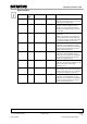
Parameter Data Type Value Range Default Description
LMN_HLM REAL LMN_LLM...
+100.0 % or
phys. variable 2
100.0
MANIPULATED VALUE HIGH LIMIT. The
manipulated value is always limited to a high
and a low limit. "Manipulated value high limit"
indicates the high limit.
LMN_LLM REAL -100.0...
LMN_HLM %
phys. variable 2
0.0 MANIPULATED VALUE LOW LIMIT. The
manipulated value is always limited to a high
and a low limit. "Manipulated value low limit"
indicates the low limit.
PV_FAC REAL 1.0 PROCESS VARIABLE FACTOR / actual
value factor. The input "Actual value factor" is
multiplied with the actual value. The input is
used for adjusting the actual value range.
PV_OFF REAL 0.0 PROCESS VARIABLE OFFSET / Actual
value offset. The input "Actual value offset" is
added to the actual value. The input is used
for adjusting the actual value range.
LMN_FAC REAL 1.0 MANIPULATED VALUE FACTOR The input
"Manipulated value factor" is multiplied with
the manipulated value. The input is used for
adjusting the manipulated value range.
LMN_OFF REAL 0.0 MANIPULATED VALUE OFFSET. The input
"Manipulated value offset" is added to the
manipulated value. The input is used for
adjusting the manipulated value range.
I_ITLVAL REAL -100.0...+100.0% or
phys. variable 2
0.0 INITIALIZATION VALUE OF THE INTEGRAL
ACTION / Initialization value for the I-
component. The output of the integrator can
be set at the input I_ITL_ON. The
initialization value is located at the input
"Initialization value for I-component".
.
DISV REAL -100.0...+100.0% or
phys. variable 2
0.0
DISTURBANCE VARIABLE. Feedforward
control is wired at the input "Disturbance
variable".
Preface Fundamentals Discontinuous Action Controller Controller Block (S)FB41 Setting the System Appendix
B3
Issued: 02/2008 Control Engineering with STEP 7