
User's Manual


Automation and Drives - SCE
T I A Training Document Page 57 of 64 Module
5.4 Exercise Example
To accommodate the system step response, a few modifications have to be made in OB 35 and
DB41. The following steps have to be performed for this:
Save your old project under a new name, and change the wiring of (S)FB 41 as follows:
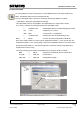
1. With STEP7, specify the manipulated value directly.
The manipulated value is to be specified in the network below in a way that with a switch
S1 (I 124.0), a selection can be made between two manipulated values.
L 0.000000e+000 //Manipulated value 0% as 32 bit floating point number
UN I 124.0 //Negation of S1 (I 124.0)
SPB M001 //Jump if RLO = 1 to label M001
L 1.000000e+002 //Manip.value 100% as 32 bit floating pt. nbr.
M001: T MD 20 //Transfer the value to flag double word MD 20
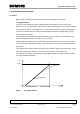
Now, for the switch position S1(I 124.0) ON, the manipulated variable y = 100%, and for OFF, the
manipulated variable y = 0%. Consequently, a step of the manipulated value from 0 to 100% can be
brought about with Switch S1. (For systems that tend to overshoot, the high manipulated value
should amount to 90% or less.).
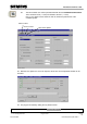
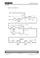
The external analog values and the manipulated value are assigned in OB1 as follows:
MAN := MD 20 //Specify the manipulated value as manual value
PV_PER := PEW 130 //Actual value x
LMN_PER := PAW 128 //Manipulated variable y
Switch manipulated value to manual
mode
Preface Fundamentals Discontinuous Action Controller Controller Block (S)FB41 Setting the System Appendix
B3
Issued: 02/2008 Control Engineering with STEP 7