
Installation Instructions


Document No. 553-680
Installation Instructions
October 9, 2019
Information in this document is based on specifications believed correct at the time of publication. The right is reserved to make changes as
design improvements are introduced. TALON is a registered trademark of Siemens Industry, Inc. Desigo® and Desigo® CC are registered
trademarks of Siemens Schweiz AG. Other product or company names mentioned herein may be the trademarks of their respective owners.
© 2019 Siemens Industry, Inc. All presented offerings are subject to a cyber security disclaimer which is available at:
www.siemens.com/bt/cyber-security.
Siemens Industry, Inc.
Smart Infrastructure
1000 Deerfield Parkway
Buffalo Grove, IL 60089-4513
USA
Tel. 1 + 847-215-1000
Your feedback is important to us. If you have
comments about this document, please send them
to SBT_technical.editor.us.sbt@siemens.com.
Document No. 553-680
Printed in the USA
Page
4 of 4
Completing the Installation
NOTE:
Do not connect the power or network
communication cable until instructed to do so
during start-up.
1. Terminate power wiring to the 24 Vac removable
plug.
2. If required, remove the RS-485 plug and terminate
the communication wiring.
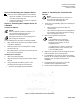
3. If required, terminate wiring to the TX-I/O Island
Bus connector (see Figure 2).
4. Terminate point wiring to the appropriate
connectors (see Figure 3).
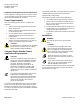
CAUTION:
Adjacent point connections on the TC
Compact Series share a Common
connection. See the Figure, Common and
Sensor Power Connections.
The combined total of the external sensor
power outputs cannot exceed 200 mA.
For specific wiring diagrams, see the TALON Wiring
Guidelines Manual (588-581).
The installation is now complete.
Figure 2. TC-36 Shared Ground Connections.
Figure 3. TC 36 with TX-I/O Island Bus—Power
and Communication Wiring.