
Installation Instructions


Document No. 553-680
Installation Instructions
October 9, 2019
Siemens Industry Inc. Page 3 of 4
Options for Mounting the Compact Series
Select one of the following options for installation:
• Mount the controller on a DIN rail by using the
four slide-out mounting tabs.
• Fasten the controller to a surface or enclosure
backplane with screws
Option 1: Mounting the Compact Series on
a DIN Rail
Installing the DIN Rail
NOTE:
Allow a minimum clearance of 3 inches (7.6
cm) around the field
panel ports and
connectors for terminating wires.
For longer DIN rails, use one mounting screw
per running f
oot of DIN rail.
Do the following if the DIN rail is not already installed:
1. Align and level the DIN rail on the mounting surface
or enclosure backplane.
2. Mark the position of the mounting holes at either
end of the DIN rail.
3. Using wall anchors, if necessary, attach the DIN rail
to the surface or backplane.
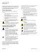
Installing the TC Compact
1. Slide out the mounting tabs.
2. Align the channel on the back of the device with the
DIN rail.
3. Using a flat-blade screwdriver, push in each
mounting tab until it clips onto the DIN rail.
• Continue with Completing the Installation.
Option 2: Fastening the Controller with
Screws
NOTE:
Allow a minimum clearance of 3 inches
(7.6
cm) around the
field panel ports and
connectors for terminating wi
res.
1. Select one of the following options for fastening the
TC Compact:
• Drive screws through the four slide-out
mounting tabs.
• Drive screws through the two mounting holes in
the controller cover and through two mounting
tabs at the opposite corners.
2. Slide out the required mounting tabs.
NOTE:
• For installation on an enclosure
backplane, use the 3/8” self-tapping
screws and, if necessary, the 1-3/4”
self-drilling screws.
• For mounting on a surface, use the 3/4”
self-drilling screws and, if necessary, the
1-3/4” self-drilling screws.
3. Align the TC Compact on the mounting surface and
mark the position of the mounting holes.
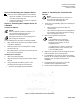
4. For installation in an enclosure, align the mounting
holes of the TC Compact with holes in the perforated
backplane. See the Figure Dimensions for
Installation.
5. Using wall anchors if necessary, secure the
controller using the provided screws.
6. Continue with Completing the Installation.
Figure 1: Compact 16/24 Dimensions for Installation.