
Operating Instructions

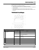

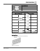

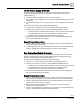

Table Of Contents
- How to Use This Manual
- Chapter 1—Introduction
- Chapter 2—Hardware Features
- 16- and 24-Point Compact Series Diagram
- 36-Point Compact Series Product Diagram
- Supported Point Types
- Compact Series Backup Batteries
- Using Auto Restore and Database Backup to Flash
- Memory
- Communication Connections
- Compact Series Smoke Control Application Requirements
- HOA (Hand-Off-Auto) Upgrade Kits
- PXM10S/T Product Overview and Description
- Unitary Equipment Controller
- TX-I/O Product Range Overview
- PX Series Enclosures and Service Boxes
- Chapter 3—Applications
- Chapter 4—Troubleshooting
- Glossary
- Index

Chapter 2—Hardware Features
TX-I/O Product Range Overview
0
65 |
93
Siemens Industry, Inc.
Owner's Manual
588-682
Building Technologies
2019-01-25
The design of the TX-I/O Modules provides optimum diagnostics and results in a more
efficient installation and maintenance workflow.
● Field wiring may be terminated prior to installation of electronics.
● Connected peripheral devices can be measured without affecting or being affected
by the I/O module.
● Hot-swappable electronic components allow powered electronics to be
disconnected and replaced without removing terminal wiring or disturbing the self-
forming bus.
TX-I/O Module Product Diagram
TX-I/O Module Symbols and Status LEDs
LED, Symbol, or Feature
LED or Symbol
Indication
1
Address key and module status
LED (green)
-
Module status as a whole (as opposed to the I/O points).
ON
Normal operation. 24 Vac (supply voltage) input present; fuse is
intact.
OFF
Error.
- No 24 Vac (supply voltage) input.
- Fuse is blown.
Flashing or pulsing
- Fault indication
- No address key
- Remote override
2 I/O point numbers
-
-
3 Terminal number
-
-
4 Test terminal
-
5 Connection terminals
-
6
-
System neutral.
-
Configurable point.