
Installation Instructions

Document No. 553-653
Installation Instructions
December 15, 2010
Information in this document is based on specifications believed correct at the time of publication. The right is reserved to make changes as design
improvements are introduced. TALON is a registered trademarks of Siemens Industry, Inc. Other product or company names mentioned herein may be
the trademarks of their respective owners. © 2010 Siemens Industry, Inc.
Siemens Industry, Inc.
1000 Deerfield Parkway
Buffalo Grove, IL 60089-4513
U.S.A
Your feedback is important to us. If you have
comments about this document, please send them to
sbt_technical.editor.us.sbt@siemens.com.
Document No. 553-653
Printed in the U.S.A.
Page 4 of 4
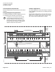
Completing the Installation
37 38 39 4025 26 27 28 29 30 31 32 33 34 35 36
24V 24VUI1 UI2 UI3 U4 U5 U6 U7 U8
PXC0009R2
Point 1 (UI) +
-
Point 2 (UI) +
Point 3 (UI) +
-
Point 4 (U) +
Point 5 (U) +
-
Point 6 (U) +
Point 7 (U) +
-
Point 8 (U) +
+
-
+
-
External Sensor Power
Supplies 24Vdc, up to 200mA
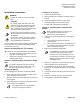
CAUTION:
terminal is connected to reference wire.
Protective ground terminal may be connected
to earth ground.
Do not connect the power or network
communication cable until instructed to do so
during start-up.
1. Terminate power wiring to the 24 Vac removable
plug.
2. If required, remove the RS-485 plug and terminate
the communication wiring.
3. Terminate point wiring to the appropriate
connectors.
CAUTION:
Adjacent point connections on the TC
Compact share a Common termination.
The combined total of the external sensor
power outputs cannot exceed 200 mA.
For spe
cific wiring diagrams, see the TALON Wiring
Guidelines for Field Panels and Equipment Controllers
(588-581).
The installation is now complete.