TC Modular Series Owner's Manual 588-781 2018-10-01 Building Technologies
Copyright Notice Copyright Notice Notice Document information is subject to change without notice by Siemens Industry, Inc. Companies, names, and various data used in examples are fictitious unless otherwise noted. No part of this document may be reproduced or transmitted in any form or by any means, electronic or mechanical, for any purpose, without the express written permission of Siemens Industry, Inc. Warning This equipment generates, uses, and can radiate radio frequency energy.
Copyright Notice To the Reader Your feedback is important to us. If you have comments about this manual, please submit them to: SBT_technical.editor.us.sbt@siemens.com Credits TALON is a registered trademark of Siemens Industry, Inc. Desigo® and Desigo® CC™ are registered trademarks of Siemens Schweiz AG. Other product or company names mentioned herein may be the trademarks of their respective owners. Printed in the USA.
Table of Contents Cyber security disclaimer ................................................................................................ 3 How to Use This Manual............................................................................................. 7 Chapter 1—Introduction............................................................................................ 10 Modular Product Overview ............................................................................................
Siemens Industry FLN ......................................................................... 25 Communication Drivers to Non-Siemens Networks ............................ 26 Modular Series Specifications ....................................................................................... 26 Modular Series Smoke Control Application Requirements ........................................... 28 PXM10S/T Product Overview and Description .............................................................
User Access and Privileges................................................................................. 67 Controlling User Access to Field Panel Functions ............................... 67 Customized Applications ............................................................................................... 67 SNMP ............................................................................................................................ 67 Chapter 4—Troubleshooting ...................................
How to Use This Manual How to Use This Manual About This Manual This manual is written for the owner and user of the TC Modular Series. It is designed to help you become familiar with the TC Modular and its applications. This section covers manual organization, document conventions and symbols used in the manual, how to access help, related publications, and any other information that will help you use this manual.
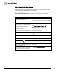
How to Use This Manual When Using TALON View Software TALON View 3.x Documentation. To view TALON View 3.x documentation, see the TALON View Online Documentation window, which you can access from the TALON View Main Menu or the TALON View program group. Document Conventions The following table lists conventions to help you use this manual in a quick and efficient manner. Convention Examples Numbered Lists (1, 2, 3…) indicate a procedure with sequential steps. 1. Turn OFF power to the field panel. 2.
How to Use This Manual Safety Symbols The following table lists the safety symbols used in this manual to draw attention to important information. Symbol Meaning Description NOTICE CAUTION Equipment damage may occur if a procedure or instruction is not followed as specified. (For online documentation, the NOTICE displays in white with a blue background.) CAUTION Minor or moderate injury may occur if a procedure or instruction is not followed as specified.
0 Chapter 1—Introduction Modular Product Overview Chapter 1—Introduction Chapter 1 provides an introduction to the TC Modular Series and how it is integrated with the TALON Automation System.
Chapter 1—Introduction Ordering Information 0 Optional Licenses Product Number Description PXF-TXIO.T License to enable the Island Bus on the TC-1000. Included with FW 3.5.1 and higher LSM-FPWEBPL.T License to enable any Siemens ALN controller to supply the host controller with data for FIN Builder graphics LSM-FPWEBPLHST.T License to enable a TC Modular or TC-36 to host FIN Builder graphics APOGEE Systems Optional Licenses Product Number Description PXF-TXIO.
0 Chapter 1—Introduction Principles of Field Panel Operation Accessories Product Number Description TXA1.K12 One set of address keys, numbers 1-12. TXA1.K24 One set of address keys, numbers 1-24. TXA1.K-48 One set of address keys, numbers 25-48. TXA1.K-72 One set of address keys, numbers 49-72. TXA1.LLT-P100 Labels for TX-I/O, 100 sheets/pack, letter format. TXA1.LH Replacement label holders.
Chapter 1—Introduction Principles of Field Panel Operation 0 If the temperature rises to 85°F (29°C) at any time, the TC Modular sends an alarm message to an alarm printer. These specifications can be met by: 1. Connecting a room temperature sensor/transmitter and fan starter output to the TC Modular. 2. Defining the room temperature sensor with a high alarm limit of 85°F (29°C) and the fan points in the TC Modular database. 3. Writing a short control program that defines your control strategy. 4.
0 Chapter 1—Introduction TALON Automation Networking License Manager Definitions ● ● ● ● ● A feature is an application or additional functionality that can be added to a field panel without the need to replace the hardware. Some features require a firmware flash. A license is the code provided by Siemens Industry to unlock a feature. The ID_STRING is a unique identifier that distinguishes an individual piece of hardware.
Chapter 1—Introduction TALON Automation Networking 0 Automation Level Network The TALON Automation Level Network (ALN) provides field panel-to-field panel and TALON View workstation-to-field panel communication. The ALN types are: ● BACnet/IP ALN ● BACnet Master-Slave/Token Passing (MS/TP) ALN Simultaneous ALN Access More than one operator or field panel can access the network at one time.
0 Chapter 1—Introduction TALON Automation Networking BACnet/IP Automation Level Network BACnet field panels communicate over a customer's Ethernet cabling and IP network using the ASHRAE Building Automation and Control Networking (BACnet) protocol. ● One TALON View workstation can administer up to 64 Ethernet-based BACnet/IP ALNs. ● Up to 100 BACnet/IP field panels can reside on a BACnet/IP network (1000 maximum per TALON View workstation). Figure 2: BACnet/IP ALN Network Example.
Chapter 1—Introduction TALON Automation Networking 0 Figure 3: BACnet MS/TP ALN with MS/TP FLN Network Example. Field Level Network The TALON Field Level Network (FLN) is a data communications network that passes information between an FLN device or devices and an Automation Level Network (ALN) device, usually within one building. FLNs consist of devices that communicate using MS/TP. Siemens Industry, Inc.
0 Chapter 2—Hardware Features TALON Automation Networking Chapter 2—Hardware Features Chapter 2 describes the TC Modular Series components and functions, as well as the enclosure used for the TC field panel series.
Chapter 2—Hardware Features TALON Automation Networking 0 Modular Series Features, Symbols, and Status LEDs. Label LED, Symbol, or Feature Status Indication 8 RUN (green) ON Normal operation. 24 Vac power is ON and the application firmware has booted. OFF Error: - 24 Vac input is not present. - Power is ON, but the application firmware has not booted. FLT (red) (for future use) - - BAT (red) ON Error: Backup battery is low. Replace the battery. OFF Normal operation.
0 Chapter 2—Hardware Features TALON Automation Networking Expansion Module Product Diagram LED, Symbol, or Feature Status Indication 1 S-+ -- MS/TP Field Level Network (FLN) ports. 2 Expansion connector -- Connection for future expansion devices. 3 RUN (green) ON Normal operation. 24 Vac power is ON and the module firmware has booted. OFF Error. TX (yellow) and RX (yellow) ● 24 Vac input is not present. ● Power is ON, but the module firmware has not booted.
Chapter 2—Hardware Features TALON Automation Networking 0 AA Battery CAUTION Batteries Failure to change DEAD alkaline battery will eventually result in battery leakage, causing permanent damage and loss of building control. Failure to change a DEAD lithium battery will result in loss of trend and database if not backed up, causing loss of data or building control. Establish a preventative maintenance schedule based on expected battery usage and life cycle.
0 Chapter 2—Hardware Features Memory – If the field panel resides on an ALN with a TALON View workstation, the TALON View workstation sets the time-date when the field panel returns to the network. – If the field panel resides on an ALN without a TALON View workstation, the time-date is synchronized with the network time during the next automatic daily time update. For more information on time synchronization, see the TALON Firmware User's Manual (588-580) (588-580).
Chapter 2—Hardware Features Memory 0 – When auto-restore is enabled, a coldstart does not result in the same downtime as with earlier revisions of TALON firmware. Because there is no waiting on a full download from the backup system, the database is restored from flash so quickly that there is little to no downtime. However, the accumulated trend data is deleted from memory. – Database restoration from flash is disabled by default.
0 Chapter 2—Hardware Features Communication Connections Random Access Memory (RAM) Synchronous Dynamic Random Access Memory (SDRAM) is the working memory of the TC Modular. When the TC Modular has booted and is operating normally, the TALON firmware, the PPCL control program, the point database, and trend data have been transferred from Flash ROM.
Chapter 2—Hardware Features 0 Communication Connections ● ● ● Connecting a machine interface device, such as an operator terminal or a textbased operator terminal, to the TC Modular. Executing firmware flash upgrades. 1200 bps to 115.2 Kbps communication is supported. NOTE: The communication speed of the port must match the communication speed of the device connected to it. USB Device Port The USB Device port supports a generic serial interface for an HMI or Tool device.
0 Chapter 2—Hardware Features Communication Connections Communication Drivers to Non-Siemens Networks As an option, the TC Modular can communicate to related building system controllers, such as boilers, chillers, rooftop units, Programmable Logic Controllers (PLCs), power meters, lighting panels, fire alarm and life safety systems, and access control systems. Modular Series Specifications Dimensions (L × W × D) TC Modular 7.56" × 3.54" × 2.76"(192 mm × 90 mm × 70 mm) 1.26" × 3.54" × 2.
Chapter 2—Hardware Features 0 Communication Connections FLN devices on the Expansion Module Electrical Rating Power Requirements 24 Vac +/-20% input @ 50/60 Hz Power Consumption (Maximum) 24 VA @ 24 Vac AC Power NEC Class 2 Communication NEC Class 2 Operating Environment Ambient operating environment Operate in a dry location, which is protected from exposure to salt spray or other corrosive elements. Exposure to flammable or explosive vapors must be prevented.
0 Chapter 2—Hardware Features Communication Connections Modular Series Smoke Control Application Requirements CAUTION The 115V or 230V PX Series Service Box is required for UL864 and NFPA92A compliant installations. For more information, see the PX Series Service Box Assemblies Installation Instructions (553-131) or the Service Box Installation Instructions (586-135). For non-UL864 and non-NFPA92A applications, any 24 Vac Class 2 transformer can be used.
Chapter 2—Hardware Features Communication Connections 0 Figure 5: Smoke Control Layout for Modular with TX-I/O Island Bus on Vertical DIN Rails. PXM10S/T Product Overview and Description NOTE: All figures show the BACnet version of the PXM10S and PXM10T. The appearance of the proprietary version may differ slightly. PXM10S and PXM10T are optional controller mounted Operator Display modules that provide a password protected user interface.
0 Chapter 2—Hardware Features Communication Connections Product Description The PXM10S and PXM10T modules are available as an upgrade for use with all Siemens Compact and Modular Series field panels to provide additional local operator capabilities. The PXM10S and PXM10T modules are field mounted and replace the field panel covers. There are three dedicated buttons, ALARM, INFO, ESC and one push DIAL.
Chapter 2—Hardware Features 0 Communication Connections If a field panel is coldstarted or it’s the first time the panel is powered up, it takes approximately 15 to 30 seconds after connection before the PXM10S and PXM10T module is operational. Requirements System Requirements The PXM10S and PXM10T modules can be used with Compact platforms (TC-36, TC24, and TC-16), as well as with the TC Modular field panels. ● All hardware must be installed. ● Power must be available to all devices.
0 Chapter 2—Hardware Features Communication Connections Operator Display Layout Display screen – Displays splash screen with either PXM10S or PXM10T module, device Firmware Revision, field panel Firmware Revision number, and Cimetrics BACstac revision number. Cursor position is indicated by either a right-angled bracket (>) or inverted text color, depending on field panel type and revision.
Chapter 2—Hardware Features Communication Connections 0 ● ● Alarm button. Provides direct access to the list of unacknowledged alarms. Alarm menu. Displays any point in alarm, regardless if it has been acknowledged or not and provides three generic filters: – Unacknowledged Alarms filter allows you to filter all alarms and lists only unacknowledged alarms in local system. – All Alarms filter allows you to view all acknowledged and unacknowledged alarms in the system.
0 Chapter 2—Hardware Features Communication Connections Main Menu Structure All menu screen captures in this manual reflect the PXM10S module. Not all menu options/features shown are available with the PXM10T module. NOTE: A solid DOWN arrow in the top right corner of the display screen indicates more menu options are available and a solid UP arrow indicates more items are available after the last highlighted item.
Chapter 2—Hardware Features 0 Communication Connections NOTE: Default user account login information for PXM10S or PXM10T is on a per ALN account basis. If your network contains an assortment of field panels with Firmware Revisions earlier than 3.2.2, the AutoLogin account is not replicated or passed onto other field panels. For more information about workstation user accounts, see the TALON ViewOnline Help system.
0 Chapter 2—Hardware Features Communication Connections Language ID PPCL N (No_access) R (Read_only) C (Command) E (Edit) (default setting) FLN devices N (No_access) R (Read_only) C (Command) E (Edit) (default setting) Equipment Scheduler N (No_access) R (Read_only) C (Command) E (Edit) (default setting) System N (No_access) R (Read_only) C (Command) E (Edit) (default setting) Diagnostics N (No_access) R (Read_only) C (Command) E (Edit) (default setting) Users N (No_access) R (Read_only) C (Co
Chapter 2—Hardware Features 0 Communication Connections Example >User initials : tiny >Account name : PXM10TINY---------------------->Password : ?????--------->Verify password : ?????--------->System, User namespace : U >Access group(s) : 1..
0 Chapter 2—Hardware Features Communication Connections Menu/Submenu Step Splash screen/logo Press the dial. Login Description Rotate the dial to highlight Automatic Login. Login menu displays. Press the dial to select Automatic Login. System logs you into the Main menu of the module. Figure 10: Main Menu Manual Login Do the following to manually log in to the PXM10S or PXM10T module. The default language for manual login is U.S. English.
Chapter 2—Hardware Features Communication Connections Menu/Submenu Step 0 Description Press the dial twice to move to the PWD fields. For PWD, rotate the dial highlight each character. Press the dial to select a character. Repeat until you enter the complete password. NOTE: If you need to return to the previous editable field, for example from PWD fields back to USR fields, press ESC. To proceed to the next field, press the dial. Press the dial to confirm USR and PWD.
0 Chapter 2—Hardware Features Communication Connections Menu/Submenu Step Description Main Rotate DIAL to highlight Logoff. Press DIAL/OK to and select Logoff. Confirm Logoff Are you sure? Displays the Logoff submenu. Rotate DIAL to highlight Yes or No. Press DIAL/OK to make selection. Confirms logoff and returns to splash screen. NOTE: If you press ESC, you are prompted with the same Confirm Logoff screen.
Chapter 2—Hardware Features 0 Communication Connections Menu/Submenu Step Description Rotate DIAL to highlight the last point (bottom of screen), and then rotate DIAL once more. Refreshes the screen and displays the previous screens last highlighted point, as well as the next series of points. Repeat steps until you reach the end of the point list.
0 Chapter 2—Hardware Features Communication Connections Figure 16: Point Action Command Submenu Menu/Submenu Step Description Main Rotate DIAL to highlight Points. Press DIAL/OK to select Points. Displays the Points menu. Points Press DIAL/OK to highlight desired point. Displays the Point Action Command submenu. Point Action Rotate DIAL to highlight Command. [selected point name] Press DIAL/OK to select Command. Displays the point name in title.
Chapter 2—Hardware Features Communication Connections 0 Releasing Points Do the following to change a point priority and release a point. Figure 19: Point Action Release Priority Submenu Menu/Submenu Step Description Main Rotate DIAL to highlight Points. Press DIAL/OK to select Points. Points Displays the Points menu. Rotate DIAL to highlight desired point. Press DIAL/OK to select point. BACnet Point Action Displays the Point Action Release Priority submenu.
0 Chapter 2—Hardware Features Communication Connections Configuring Point Monitor NOTE: This application and its sub-features are only available with the PXM10S module. The Point Monitor allows you to select the points you frequently need to monitor and allows quick access to view a point status. This concept is similar to a Favorites list. The maximum number of points listed and stored in Point Monitor is 10. You cannot add more points to the Point Monitor once you reach the maximum number.
Chapter 2—Hardware Features Communication Connections 0 Figure 22: Configure Submenu Figure 23: Edit Point Monitor Submenu Do the following to configure bundled points in Point Monitor. Menu/Submenu Step Main Rotate DIAL to highlight Point Monitor. Point Monitor Description Press DIAL/OK to select Point Monitor. Displays the Point Monitor menu. Rotate DIAL/OK to highlight Configure. Displays all available points at the field panel. Press DIAL/OK to select Configure.
0 Chapter 2—Hardware Features Communication Connections Menu/Submenu Step Description Main Rotate DIAL to highlight Point Monitor. Press DIAL/OK to select Point Monitor. Point Monitor Rotate DIAL to highlight Reset. Press DIAL/OK to select Reset. Remove Monitor Displays the Point Monitor menu. Displays the Remove Monitor submenu. Rotate DIAL to highlight point. Press DIAL/OK to make select point.
Chapter 2—Hardware Features Communication Connections Menu/Submenu Step Main Rotate DIAL to highlight Point Monitor. Description Press DIAL/OK to select Point Monitor. Point Monitor 0 Displays the Point Monitor menu. Rotate DIAL to highlight Display. Press DIAL/OK to select Display. Displays the Display submenu. Displays the monitored points; one point and its value per line. Up to 10 points can be added the Point Monitor list. Display Press ESC. Returns you to the Monitor menu.
0 Chapter 2—Hardware Features Communication Connections Menu/Submenu Step Description Press DIAL/OK to select Adjust Brightness. Rotate DIAL to select a value. Valid brightness values are 0 through 100. Press DIAL/OK to make selection. Applies the value and returns you to the previous menu. Press ESC. Returns you to the Settings menu without applying the new value. Figure 29: Brightness Submenu Color NOTE: The Color feature is available only for the PXM10S module.
Chapter 2—Hardware Features Communication Connections 0 Figure 31: Color Submenu Timeout The PXM10S and PXM10T modules automatically turn off the backlight on the Display screen after a predetermined amount of inactivity. However, when you press any key, the backlight turns on again. If Point Monitor was active on the screen during this time, the point list is saved, even if you are logged off. Do the following to modify the Timeout feature.
0 Chapter 2—Hardware Features TX-I/O Product Range Overview TX-I/O Product Range Overview TX-I/O™ is a range of I/O modules, with associated power and communication modules, for use within the TALON System. The I/O modules communicate between the TC Modular or the TC-36 and the related devices in the building services plant. The TX-I/O product range includes the following: ● Eight types of I/O modules, which act as signal converters. ● TX-I/O Power Supply for the TX-I/O modules.
Chapter 2—Hardware Features TX-I/O Product Range Overview 0 TX-I/O Module Product Diagram TX-I/O Module Symbols and Status LEDs LED, Symbol, or Feature 1 Address key and module status LED (green) LED or Symbol - Indication Module status as a whole (as opposed to the I/O points). ON Normal operation. 24 Vac (supply voltage) input present; fuse is intact. OFF Error. - No 24 Vac (supply voltage) input. - Fuse is blown.
0 Chapter 2—Hardware Features TX-I/O Product Range Overview TX-I/O Module Symbols and Status LEDs LED, Symbol, or Feature LED or Symbol Flashing or pulsing Indication - Override action - Remote override - Output: Local override is off, operation is not possible. - Input: Operation is not possible. 8 LCD signal panel - Only on a TX-I/O modules with –ML suffix. 9 Local override switch - Only on a TX-I/O with –M or –ML suffix.
Chapter 2—Hardware Features 0 TX-I/O Product Range Overview TX-I/O LCD Panel by Point Type. Point Type (Displays in LCD Bottom Row) Normal Operation (Displays in LCD Top Row) Analog Input, Current Low or high value Analog Input, Resistance Temperature Analog Input, Voltage Low or high value Analog Output, Current Low or high value Analog Output, Voltage Low or high value Digital Input, Counter The picture can't be displayed.
0 Chapter 2—Hardware Features TX-I/O Product Range Overview The keys are available in sets of 24, up to a maximum value of 72 (two sets of 12, 124, 25-48, and 49-72). ● The I/O module address is mechanically encoded in the address key. – Without an address key, the module is inactive. – With an address key inserted, the module has full functionality.
Chapter 2—Hardware Features TX-I/O Product Range Overview 0 TX-I/O Power Supply Overview The TX-I/O Power Supply bridges communication and power from one DIN rail to another and generates 28.8 W (1.2A at 24 Vdc) to power TX-I/O modules and peripheral devices. ● An LED provides an indication of 24 Vdc on the TX-I/O bus. ● Up to 4 TX-I/O Power Supplies can be operated in parallel, with a maximum of two per DIN rail. ● It can be located within a row of TX-I/O modules or at the beginning of a new DIN rail.
0 Chapter 2—Hardware Features PX Series Enclosures and Service Boxes PX Series Enclosures and Service Boxes PX Series enclosures house both electronic and pneumatic components. The enclosures include a perforated backplane for mounting TC Series field panels or other electronic or pneumatic components. General features of the enclosures include: ● Availability in three sizes to match installation needs: 18-, 19-, and 34-inch.
Chapter 2—Hardware Features PX Series Enclosures and Service Boxes 0 Figure 35: PX Series Service Box (115V), 34-inch enclosure. Figure 36: PX Series Service Box (115V), 19-inch enclosure. Siemens Industry, Inc.
0 Chapter 2—Hardware Features PX Series Enclosures and Service Boxes Figure 37: PX Series Service Box Connectors. ● ● Each Service Box distributes the total 24 Vac power provided to the plug-in terminations on the left side. – Two Class 1 power-limited terminations distribute up to the total power to controllers and power supplies inside the same enclosure. – Earth ground is provided on the CTLR termination.
Chapter 2—Hardware Features PX Series Enclosures and Service Boxes 0 PX Series Enclosure Specifications PX Series 18" Enclosure Specifications Dimensions (H × W × D) 18" × 14" × 6" (457.2 mm × 355.6 mm × 152.
0 Chapter 2—Hardware Features PX Series Enclosures and Service Boxes PX Series Service Box Specifications Power Requirements for 115 Vac Service Boxes PXA-SB115V192VA Input: 115 Vac +/- 15%, 50/60 Hz +/- 5%, 220VA maximum, 2A CB Output: 24 Vac +/- 20%, 50/60 Hz +/- 5%, 192VA maximum PXA-SB115V384VA Input: 115 Vac +/- 15%, 50/60 Hz +/- 5%, 440VA maximum, 4A CB Output: 24 Vac +/- 20%, 50/60 Hz +/- 5%, 384VA maximum 115 Vac models also have a duplex outlet, which is protected by Mains 20A or 15A CB for use
Chapter 2—Hardware Features PX Series Enclosures and Service Boxes Siemens Industry, Inc.
0 Chapter 2—Hardware Features PX Series Enclosures and Service Boxes ● ● ● 62 | 79 Siemens Industry, Inc. Building Technologies Space between door panel and opening obstruction must be at least 11 inches (279.4 mm) to allow for door removal at 40 degrees, or 28 inches (711 mm) with a cabinet mounting at least 19 inches (483 mm) from the left side wall to allow door to completely open at 135 degrees.
Chapter 3—Applications Operator Interface Chapter 3—Applications Chapter 3 describes the program and applications provided with or available for the TC Modular Series.
Chapter 3—Applications Powers Process Control Language (PPCL) Control Program and Point Database Network Layout ● ● ● View network layout Navigate to other Web-enabled panels Search database for individual points System Status Bar ● ● ● Visual indication of new alarms and unacknowledged alarms Visual indication of out of service, faults, and failed devices Ability to view, filter, and acknowledge system alarms from a single page Point Commanding ● ● ● Change point values Place points “Out of Service
Chapter 3—Applications Applications Control Programs The control programs define all user-defined control logic, calculations, applications, and so on for the TC Modular. PPCL is written in an English-based programming language called Powers Process Control Language (PPCL). It is a powerful programming language developed specifically for controlling Heating, Ventilating, and Air Conditioning (HVAC) equipment.
Chapter 3—Applications Applications Alarm Management An alarm is a status that indicates whether a point value or state is above or below a defined value. Alarm management is the strategy used to define, route, acknowledge, and resolve those alarms. Points are defined as alarmable for the following reasons: ● To prevent critical problems. Points that affect human safety or can cause a severe problem in building operation should be defined as alarmable.
Chapter 3—Applications Customized Applications User Access and Privileges A user issues commands or requests to the TC Modular Series using an operator terminal and the operator interface program that resides in the TC Modular Series. The operations that a particular user can perform depend on the access level assigned to each field panel function in their user account. User accounts are used to manage access and security for field panels on a specified Automation Level Network (ALN).
Chapter 3—Applications SNMP SNMP is an application layer protocol that facilitates the exchange of management information between network devices. It is part of the Transmission Control Protocol/Internet Protocol (TCP/IP) suite. SNMP enables network administrators to manage network performance, find and solve network problems, and plan for network growth. Three versions of SNMP exist: SNMP version 1 (SNMPv1), SNMP version 2 (SNMPv2), and SNMP version 3 (SNMPv3).
Chapter 4—Troubleshooting Service Information Chapter 4—Troubleshooting NOTE: The following information is for qualified service personnel only. Chapter 4 describes corrective measures you can take if you encounter a problem with a TC Modular Series controller. If you encounter a symptom or a problem not covered in this manual, contact your Siemens Solution Partner, Authorized TALON Dealer.
Chapter 4—Troubleshooting Service Information Electrostatic Discharge An electrostatic discharge (ESD) wrist strap is generally not required when installing or servicing a TC Modular. However, if the field panel is installed in a very dry environment where a high static discharge is likely, an ESD wrist strap is recommended. Error Status Messages For error status message descriptions, see the TALON Firmware User's Manual (588580) (588-580).
Chapter 4—Troubleshooting Troubleshooting Modular Field Panels Reinstalling the Mounting Tabs Do the following to reinstall a DIN mounting tab: 1. Place the wire spring clip into the pocket in the channel for the mounting tab. 2. Make sure the mounting tab is face down. 3. Working from the center (inside) of the base, slide the mounting tab into the channel. (See the following figure.) NOTE: The end with the screw hole slides into the channel first. Figure 39: Reinstalling a DIN Mounting Tab.
Chapter 4—Troubleshooting Troubleshooting Modular Field Panels CAUTION If you do not have a current backup, save the database before continuing. 1. Check that the mylar insert was removed from the AA (LR6) battery holder. 2. Check for polarity (+ to +) and (- to -). 3. Check that the battery is properly seated in the battery holder. 4. Replace the battery. RUN LED The RUN LED is on solid.
Chapter 4—Troubleshooting Troubleshooting the TX-I/O Island Bus Troubleshooting the TX-I/O Island Bus All points on the TX-I/O island bus are failed. 1. Verify all three signals, System Neutral ( ), Communication Data (CD), and Communication Supply (CS) are connected throughout the entire TX-I/O island bus. The 24 Vac LED on the TX-I/O Power Supply is OFF. 1. Check for 24 Vac input. 2. Replace the fuse (4A, 5 × 20 mm, 250V, medium-acting, ceramic fuse).
Glossary Glossary The glossary contains terms and acronyms that are used in this manual. 1 100Base-TX: Fast Ethernet network implementation. 100Base-TX stands for 10Mbps baseband twisted-pair cable. The “X” stands for 100Base-X, the IEEE identifier for the media system used by 100Base-TX. 10Base-T: Ethernet network implementation. 10Base-T stands for 10Mbps baseband twisted-pair cable. A alarm priority: Ranking of a point alarm.
Glossary Domain Name Server (DNS): Common method of assigning computer names in UNIXbased networks. A DNS server maintains a list of host names and IP addresses, allowing computers that query them to find remote computers by specifying host names rather than IP addresses. DNS is a distributed database; therefore, DNS servers can be configured to use a sequence of name servers, based on the domain in the name being looked for.
Glossary P Plain Old Telephone Service (POTS): Acronym for the standard telephone service that is used in most homes. Communication speed is generally restricted to 52K bps. point condition: State of a point such as normal, alarm, alarm-by-command, failed, operator disabled, or proofing. R Read Only Memory (ROM): Non-volatile, permanent, but field-programmable memory that stores the operating system of the field panel.
Index Index 1 10B/100B Ethernet port........................................... 25 A F Field Level Network (FLN) ...................................... 17 Flash Read-Only Memory (Flash ROM) .................. 22 agency listings ........................................................ 27 alarm management ................................................. 66 applications alarm management .............................................. 66 customized applications .......................................
Index troubleshooting 24 Vac LED .......................................................... 73 BATT LOW LED ................................................... 71 I/O module status LED ......................................... 73 RUN LED .............................................................. 72 TX-I/O product range .............................................. 50 TX-I/O Product Range power and bus modules ....................................... 54 U USB Device port ..............................
Issued by Siemens Industry, Inc. Building Technologies Division 1000 Deerfield Pkwy Buffalo Grove IL 60089 +1 847-215-1000 Document ID: 588-781(DA) Edition: 2018-10-01 © Siemens Industry, Inc., 2018 Technical specifications and availability subject to change without notice.