
Scanner User Manual

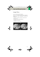
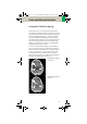

Table Of Contents
- User Documentation
- Scan and Reconstruction
- Dose Information
- Workflow Information
- Application Information
- Head
- Neck
- Shoulder
- Thorax
- Abdomen
- Pelvis
- Spine
- Upper Extremities
- Lower Extremities
- Vascular
- Specials
- Children
- Overview
- Hints in General
- HeadRoutine_Baby
- HeadRoutine_Child
- HeadSeq_Baby
- HeadSeq_Child
- InnerEar
- SinusOrbi
- Neck
- ThoraxRoutine_Baby
- ThoraxRoutine_Child
- ThoraxHRSeq_Baby
- ThoraxHRSeq_Child
- Abdomen_Baby
- Abdomen_Child
- Spine_Baby
- Spine_Child
- ExtrHR_Baby
- ExtrHR_Child
- HeadAngio
- HeadAngio08s
- CarotidAngio
- CarotidAngio08s
- BodyAngio
- BodyAngio08s
- NeonateBody
- syngo 3D
- syngo Fly Through
- syngo Dental CT
- syngo Osteo CT
- syngo Volume Evaluation
- syngo Dynamic Evaluation
Scan and Reconstruction
27
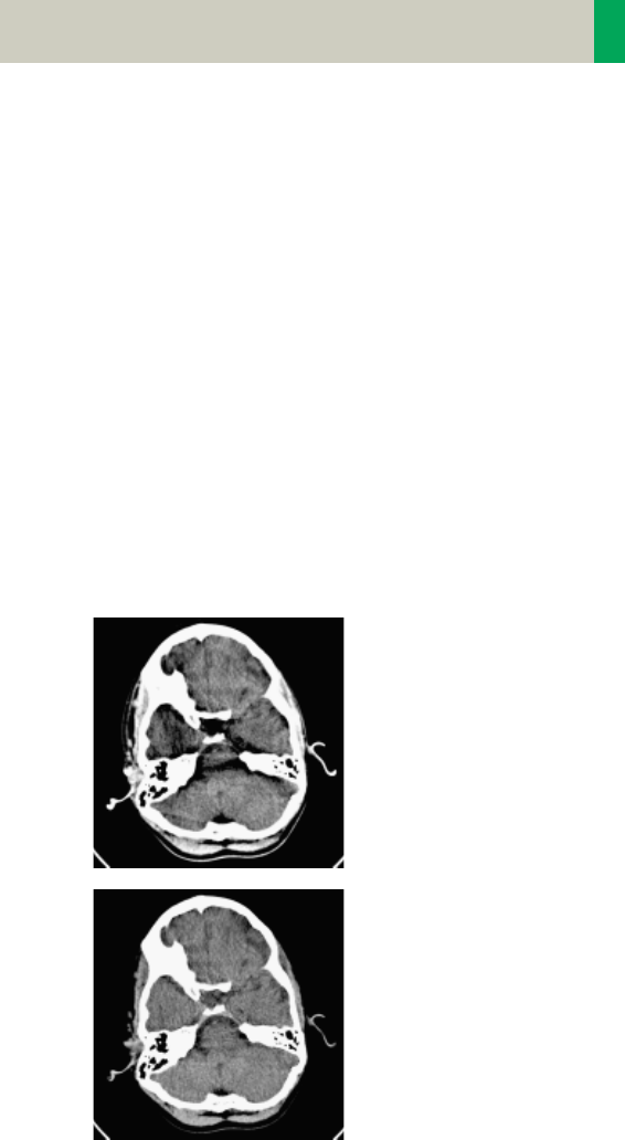
Improved Head Imaging
An automatic bone correction algorithm has been
included in the standard image reconstruction. Using a
new iterative technique, typical artifacts arising from
the beam-hardening effect, e.g., Hounsfield bar, are
minimized without any additional post-processing.
This advanced algorithm allows for excellent images of
the posterior fossa, but also improves head image
quality in general. Bone correction is activated auto
-
matically for body region “Head”.
In order to optimize image quality versus radiation
dose, scans in the body region “Head” are provided
within a maximum scan field of 300 mm with respect
to the iso-center. No recon job with a field of view
exceeding those limits will be possible. Therefore,
patient positioning has to be performed accurately to
ensure a centered location of the skull.
Head image without
correction.
Head image with cor-
rections.
C2-025.630.01.01.02_APPLICATIONGUIDE_SPIRIT.book Page 27 Friday, April 8, 2005 9:55 AM