
Instruction Manual

Siemens Building Technologies
Fire Safety
P/N 315-049480C-2
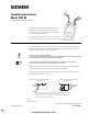
Figure 1
STRI-M Module
The Model STRI-M Series Addressable Interface
Module from Siemens Building Technologies, Inc.
interfaces direct shorting devices to the FDLC loop
circuit of the FS-250C System.
The STRI-M can monitor a normally open or closed
dry contact and it can report the status of the contact.
PROGRAMMING Refer to Figure 1 to locate the red and black FDLC loop circuit wires of the STRI-M.
Connect the Addressable Loop Driver circuit wires of the STRI-M to the Model SDPU
Programmer/Tester. Use the cable provided with the Programmer/Tester and the 2
alligator clip to banana plug adapters provided.
To Prevent Damage To The SDPU:
DO NOT connect a STRI-M to the SDPU until all field wiring is removed from the
red and black FDLC loop circuit wires of the STRI-M.
Connection from the SDPU to the STRI-M is not polarity sensitive. Refer to
Figure 3 for the proper connections to the control panel.
(Refer to Figure 2.) Follow the instructions in the SDPU Programmer/Tester Manual
(P/N 315-033260C) to program the desired address into STRI-M.
Record the device address on the label located on the STRI-M. The STRI-M can now
be installed and wired to the system.
ORG BLK
LINE
2
LINE
1
GRNORG RED
ALL CONNECTIONS ARE POWER LIMITED
EARTH
GND
STRI-M
Addressable Interface Module
Installation Instructions
Model STRI-M
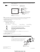
NOTES:
1. There can be any number of normally closed or normally open switches.
2. The end of line resistor must be located at the last switch.
3. Do not wire a normally closed switch across the end of line resistor.
4. Only for use with status applications.
Figure 2
Wiring Switches
NORMALLY OPEN SWITCHES
(SEE NOTES 2 AND 3 )
PROGRAMMABLENORMALLY CLOSED SWITCHES
(SEE NOTE 4)
PROGRAMMABLE
ENDOFLINE
RESISTOR
470 OHMS,
1/4W
ENDOFLINE
RESISTOR
470 OHMS,
1/4W
firealarmresources.com