
Integrated Motor/Inverter Installation and Commissiong Instructions


English 4. Clear Text Display Module & System Parameters
© STÖBER plc 199
8
05.02.01
26
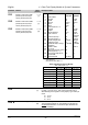
Parameter Function Range
[Default]
Description / Notes
P203 •
••
•
I gain (%) 0.00 -
99.99
[0.00]
Integral gain.
0.01% corresponds to the longest integral response time.
P205 •
••
•
Sample interval (x 25 ms) 1 - 2400
[1]
Sampling interval of feedback sensor.
P206 •
••
•
Transducer filtering 0 - 255
[0]
0 = Filter off.
1 - 255 = Low pass filtering applied to transducer.
P207 •
••
•
Integral capture range (%) 0 - 100
[100]
Percentage error above which integral term is reset to zero.
P208
Transducer type 0 - 1
[0]
0 = An increase in motor speed causes an increase in sensor
voltage/current output.
1 = An increase in motor speed causes a decrease in sensor
voltage/current output.
P210
Transducer reading (%) 0.0 - 100.0
[-]
Read only. Value is a percentage of full scale of the PI input.
P211 •
••
•
0% setpoint 0.00-
100.00
[0.00]
Value of P210 to be maintained for 0% setpoint.
P212 •
••
•
100% setpoint 0.00-
100.00
[100.00]
Value of P210 to be maintained for 100% setpoint.
P220 •
••
•
PI frequency cut-off 0 - 1
[0]
0 = Normal operation
1 = Switch off inverter at or below minimum frequency.
P331
Analogue mode 0 - 4
[2]
0 = Internal potentiometer only
1 = External analogue input only
2 = Internal potentiometer + external analogue input
3 = Internal potentiometer fine, external input coarse
4 = Internal potentiometer coarse, external input fine
P332
Fine adjustment (%) 0 - 100
[10]
Percentage of fine tuning adjustment for P331 = 3 or 4.
P700
P701 •
••
•
P702
P723
State of digital inputs 0 - 7
[-]
DIN3 DIN2 DIN1
0 =0 0 0
1 =0 0 1
2 =0 1 0
3 =0 1 1
4 =1 0 0
5 =1 0 1
6 =1 1 0
7 =1 1 1
P880
Specific to PROFIBUS-DP. See PROFIBUS Handbook for further
details. (Access only possible with P099 = 1.)
Specific to PROFIBUS-DP. See PROFIBUS Handbook for further
details. (Access only possible with P099 = 1.)