
User Guide


599 Series Zone Valve 2-way, 3-way Thermic Actuators Technical Instructions
Document Number 155-780
March 15, 2013
Information in this publication is based on current specifications. The company reserves the right to make changes in specifications and models as
design improvements are introduced. Product or company names mentioned herein may be the trademarks of their respective owners.
© 2013 Siemens Industry, Inc.
Siemens Industry, Inc.
Building Technologies Division
1000 Deerfield Parkway
Buffalo Grove, IL 60089
USA
+ 1 847-215-1000
Your feedback is important to us. If you have comments
about this document, please send them to
sbt_technical.editor.us.sbt@siemens.com
Electrical
Installation
• Observe all local installation regulations.
• Install the connecting cable downwards so that it leads away from the actuator.
• Isolate the power supply. (For example, connect an automatic circuit breaker or
switch fuse upstream of the control unit.)
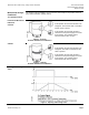
Wiring Diagram
NOTE: G: positive
G0: neutral
Figure 4. Wiring Diagram.
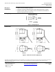
Dimensions
STA73U STP73U
Figure 5. Dimensions in Inches (Millimeters).
Document No. 155-780
Printed in the USA
Page 5