
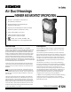
Data Sheet for Product
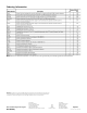

The inlet sampling tube length is determined by the
width of the air duct being protected. The inlet tube
nearest to but greater than the duct width should be used
(see table). The inlet tube can then be trimmed at the job
site to the exact width of the duct. The outlet sampling
tube for all ducts, irrespective of width, has a fixed length
of approximately 3 inches (7.5 cm) and is supplied with
the duct housing. When required, the EAD-3 weather
proof enclosure for Duct Housing is available.
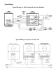
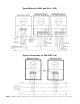
When the use of a remote relay is required, a relay
module DA-3SR for conventional systems or DA-X3SR for
MXL or ICon-1 (IXL) systems is used to replace the
existing terminal strip in the air duct housing wiring
compartment. See installation diagram.
Sampling Tube Selection Table
Maintenance of the detector is easily accomplished by
the removal of the Series 3/X3 duct housing sampling
chamber cover. The detector, which plugs into the hous-
ing, is easily removed for cleaning by a trained technician.
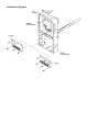
All that is necessary for the installation of the air duct
detect-or is the cutting of three small holes for the
sampling tube installation (template included) and the
drilling of four holes for mounting the air duct housing. The
unit is then easily mounted in place and connection made
to the existing wires or terminals if optional accessories
are utilized.
Engineer and Architect Specifications
The air duct housing for the fire detection system shall be
a Fire Safety Series 3/X3 air duct housing.
The air duct housing shall incorporate the use of one of
the following detectors.
Series IL Photoelectric Model ILP-1
Series IL Ionization Model ILI-1B
Series IL Ionization
(High Altitude 3000-8000 ft.) Model ILI-1BH
Series 3 Ionization Model DI-B3
Series 3 Ionization
(High Altitude 3000-8000 ft.) Model DI-B3H
Series 3 Photoelectric Model PE-3
Series ID-60 Ionization Model ID-60IB
Series ID-60 Ionization
(High Altitude 3000-8000 ft.) Model ID-60IBH
Series ID-60 Photoelectric Model ID-60P
The air duct housing unit shall be designed for detection
of combustion products and/or smoke in air conditioning
and ventilation system ducts in compliance with NFPA
Standard 90A. The assembly shall consist of a housing to
accommodate sampling tubes which extend into and
across the duct of the ventilation system.
While the fans are operating, a continuous cross-sectional
sampling of air from the duct shall flow through the
selected ionization or photoelectric detector, after which
the sampled air shall be returned to the duct.
Air handling equipment shall be shut down by a signal
from the fire detection system control equipment. When
the air duct housing incorporates the optional relay, the
shut down of air handling devices may be accomplished
by a signal directly from the detector.
The air duct housing shall be available with a self-con-
tained power supply so that it can function as a stand-
alone unit if desired. The self-contained stand-alone unit
will power and supervise two satellite units.
The air duct housing shall utilize a plug-in detector head
located in the air sampling chamber. The detector shall be
either ionization or photoelectric. There shall be provisions
to check the detector sensitivity in place under actual air
flow conditions.
The air duct housing shall be mounted directly outside of
the air duct by means of four bolts (supplied). A template
shall be provided for making necessary cut-outs and
holes. Complete instructions shall be supplied with the
unit.
The air duct housing shall be a Fire Safety Model _______
(See listing on back page) and shall be Underwriters
Laboratories, Inc. Listed, specifically for use in air
handling systems.
Note to Architect: When building codes regulate the
location of detectors within ventilating systems, make
sure that the number and locations of detectors is in
accordance with the code regulations.
(The “X” Series and the PEC-3 detectors are obsolete
as of 1/1/92. The IL Series are direct replacement for
the ID-60 and “X” Series and the PE-3 for the PEC-3.)
Dimensions