
User Manual

s Industry, Inc.
Building Technologies Division
Fire Safety
8 Fernwood Road
Florham Park, NJ 07932
Tel: (973) 593-2600
FAX: (908) 547-6877
URL: www.SBT.Siemens.com/FIS
(SII)
Printed in U.S.A.
Fire Safety
2 Kenview Boulevard
Brampton, Ontario
L6T 5E4 / Canada
Tel: (905) 799-9937
FAX: (905) 799-9858
August 2010
Supersedes sheet dated 5/10
(Rev. 3)
Specifications – (continued)
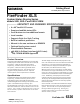
The SSD Series display has two (2) display-control buttons
that are used to display the next or the previous event
information in the sequence, and a local sounder silence
button. Programming for the SSD Series display is done
with the Zeus programming tool.
Models SSD-C and Model SSD-C-REM have three (3)
additional control buttons for acknowledging events,
silencing audible circuits, and resetting the system.
Model SSD-C has an integral key switch that enables these
control buttons to operate. Model SSD-C-REM is located
within a locked cabinet, so no additional key switch is
required for enabling the control buttons.
The SSD Series display is remotely connected to the
H-Net communication bus from any Model NIC-C interface in a
FireFinder XLS system enclosure using Class B, Style 4 or
Class A, Style 7 wiring. 24VDC is required to run the SSD
Series display, and can be provided from a Model PSC-12
Power Supply or PSX-12 Power Supply Extender in the
FireFinder XLS system enclosure. Power from other
UL Listed 24VDC power sources is also acceptable.
The SSD Series display has screw terminals capable of
supporting 12 to 22-gage wires. The H-Net
communication from the FireFinder XLS system can be
terminated on the SSD Series display, or may pass
through for communication with other modules.
Diagnostic LEDs on the SSD Series display indicate
power and communication status.
Models SSD and SSD-C can be mounted in a (2) two-gang
electrical box or a (4) four-inch square electrical box. No
flush-trim kit is required. The unit is approximately
10-1/2“(26.7cm.) wide, 6-1/8” (15.2cm.) high, and
1-1/2” (3.8cm.) deep.
The Model SSD-C-REM is mounted in a Model
REMBOX2 or Model REMBOX4 Remote Lobby Enclosure, or
any CAB enclosure inner door. Model SSD-C-REM requires
two (2) module spaces in the remote lobby enclosure,
and its bracket supports the mounting of four (4) inner
door modules (such as Model SCM-8 or Model LCM-8
modules) below the display. The inner door module spaces
are arranged in two (2) rows of (2) two-module spaces.
Details for Ordering
Model
Number
Part
Number
Description
SSD 500-034170 System-Status Display
SSD-C 500-648733 System-Status Display [with control]
SSD-C-REM
500-634773
System-Status Display [with control for
remote-lobby enclosure]
REMBOX2 500-633772 Small Remote-Lobby Enclosure
REMBOX4 500-633914 Large Remote-Lobby Enclosure
BCM 500-033320 Blank Control Module Plate
Electrical Ratings
Notes:Anauxiliary‐regulated,power‐limitedpowersupplymaybeused
toprovidepowertoModelSSD.Thepowersupplymustbe
ULListedfor
Fire‐ProtectionSignalingApplication.BesuretoalsoincludeModelSSD‐C
inthebatterycalculations.
Notes
: Anauxiliary‐regulated,power‐limitedpowersupplymaybeusedto
providepowertoModelSSD.Thepowersupplymustbe
ULListedforFire‐
ProtectionSignalingApplication.
Notes
: Anauxiliary‐regulated,power‐limitedpowersupplymaybeused
toprovidepowertoModelSSD‐C‐REM.Thepowersupplymustbe
UL/
ULCapprovedforFireProtectionSignalingApplication.Besuretoalso
includeModelSSD‐C‐REMinthebatterycalculations.
Products are UL 864 9th Edition listed for indoor dry
locations within a temperature range of 120+/-3°F
(49+/-2°C) to 32+/-3°F (0+/-2°C) and at a relative
humidity of 93+/-2% at a temperature of 90+/-3°F
(32+/-2°C).
Notice: This marketing catalog sheet is not intended to be used for system design or installation purposes.
For the most up-to-date information, refer to each product’s installation instructions.