
User Guide


MT Series SSC Electronic Valve Actuator, 24 Vac Proportional Control Technical Instructions
Document Number 155-313P25
June 7, 2013
Siemens Industry, Inc. Page 5
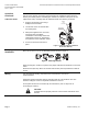
Wiring Diagrams
+
-
Y
G0
G
R1
24
Vac
NEUT
ACTUATOR
EARTH GROUND
ISOLATING CLASS 2
TRANSFORMER FOR
24 Vac POWER
120 Vac
ELECTRONIC
CONTROLLER
EA0794R2
Figure 4. SSC61U and SSC61.5U Wiring.
G, G0 24 Vac operating voltage
Y 0 to 10 Vdc control signal
G0 System neutral
G System potential
R1 500 ohm resistor
(optional for 0 to 20 mA
operation)
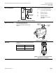
Manual Override
For manual positioning, the
manual override knob in the
center of the position indicator per
Figure 5.
CLOCKWISE
EXTENDS
SHAFT
COUNTER
CLOCKWISE
RETRACTS
SHAFT
EA1161R1
A
B
AB
Figure 5. Manual Override.
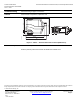
Start-up
Check the wiring and the position indicator
(
0
1
EA1158R1
Figure 6).
Position Indicator Output Shaft
0 Retracted
1 Extended
Figure 6. Top View of Position Indicator
(Shown in the 0 Position).