
Install Instructions

Document Number 129-243
Installation Instructions
December 18, 2003
Information in this publication is based on current specifications. The company reserves the right to make changes in specifications and models as
design improvements are introduced. Other product or company names mentioned herein may be the trademarks of their respective owners.
© 2003 Siemens Building Technologies, Inc.
Siemens Building Technologies, Inc.
1000 Deerfield Parkway
Your feedback is important to us. If you have
comments about this document, please send
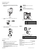
Manual Override
For manual positioning, turn the manual override knob in the
center of the position indicator. See Figure 9. Turn the wrench
clockwise to extend the actuator spindle. The actuator will
maintain its position until power is provided or restored.
NOTE: For SSB61U
If an override is performed while the power supply is
connected, the actuator will not track accurately when the
control signal is applied. A short power off/power on sequence
is recommended to recalibrate the actuator.
Document No. 129-243
Printed in the U.S.A.
EA0587R3
AB
B
A
Figure 9.
Start-up
• Check the wiring and the position indication.
• When the position indicator is on the “1” position the
output shaft is extended.
• When the position indicator is in the “0” position, the
output shaft is retracted.
EA0588R3
The "0" and "1"
position markings
are for reference
only, and not
intended for stroke
measurement.
• (A) When knob is turned
counterclockwise, the
spindle is retracted.
• (B) When knob is turned
clockwise, the spindle is
extended.
Position
indicator at 1.
Position
Indicator at 0.
Troubleshooting
Check the wiring for the proper connections.
EA0589R2
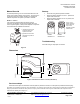
1-7/8
(48)
3-1/4
(83)
3-7/8
(98)
3-1/8
(79)
Dimensions
Figure 10. Dimensions shown in inches (millimeters).
Service envelope
Minimum access space recommended: 8 inches (200 mm) above the actuator, 8 inches (200 mm) beside the terminal plug.
Buffalo Grove, IL 60089-4513
U.S.A.
them to technical.editor@siemens.com
Page 3 of 3