
Data Sheet for Product

8/10
Siemens CE1N4893en
Smart InfrastructureBuilding Technologies 2020-05-
11
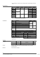
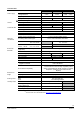
General ambient conditions Operation
EN
60721
-
3
-
3
Transport
EN
60721
-
3
-
2
Storage
EN
60721
-
3
-
1
Environmental conditions
Class 3K3
Class 2K3
Class 1K3
Temperature
+1...+50 °C
–
25...+70 °C
–
5...+50 °C
Humidity
5...85 % r.h. < 95 % r.h. 5...95 % r.h.
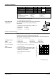
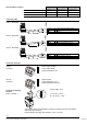
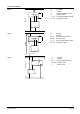
Connecting cable
7 White Y2 Control signal CLOSE (AC 230 V)
6 Black Y1 Control signal OPEN (AC 230 V)
4 Blue N Neutral
L = 2,5 m, or 4,5 m
7 Orange Y2 Control signal CLOSE (AC 24 V)
6 Violet Y1 Control signal OPEN (AC 24 V)
1 Red G System potential AC 24 V
L = 2,5 m, or 4,5 m
8 Grey Y Control signal DC 0...10 V
2 Black G0 System neutral (- DC 24 V)
1 Red G System potential AC 24 V (+ DC 24 V)
L = 2,5 m, or 4,5 m
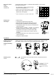
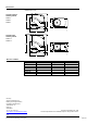
Connection terminals
4891Z32
Y
2
Y
1
G
4864Z15
Control signal CLOSE
Control signal OPEN
System potential AC 24 V
G
0
Y
G
4864Z16
System neutral
Control signal DC 0...10 V
System potential AC/DC 24 V
Q14
Q11
Q12
80125
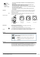
Factory setting: 50 %
0...50 % Q11 ® Q12
50...100 % Q11 ® Q14
The switching point can be adjusted by turning the switching cam with a screwdriver
(see Mounting Instructions).
Recommended connecting cable: H03VV-F, 2x0.5…0.75 mm
2
.
ASY3L.. with
SSA
31..
ASY8L.. with
SSA
81..
ASY6L.. with
SSA
61..
ASY99
for
SSA
81..
ASY100
for
SSA
61..
Terminals for auxiliary
switches
SSA31.1, SSA81.1