
User Manual

10
Siemens
A6V11858276_en--_a
Smart Infrastructure
2020-07-30
Diagrams
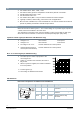
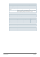
Connection terminals
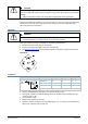
SSA131.00
Y1 = Control signal OPEN (AC 24 V)
Y2 = Control signal CLOSE (AC 24 V)
G = System potential AC 24 V
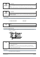
SSA331.00
Y1 = Control signal OPEN (AC 230 V)
Y2 = Control signal CLOSE (AC 230 V)
N = Neutral
SSA161.05
G = System potential AC 24 V (+ DC 24 V)
Y = Control signal DC 0...10 V
G0 = System neutral (- DC 24 V)
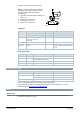
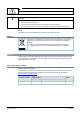
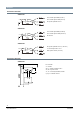
Connection diagrams
SSA131.00
N = Controller
Y = Actuator
SP, G = System potential AC 24 V
SN, G0 = System neutral
Y1, Y2 = Control signal OPEN, CLOSE
Q1, Q2 = Controller contacts