Electromotoric actuator SSA131.00, SSA331.00, SSA161.05 For pressure independent combi valves (PICV), radiator valves, MiniCombi valves (MCV) and small globe valves ● ● ● ● ● ● ● ● A6V11858276_en--_a 2020-07-30 SSA131.. Operating voltage AC 24 V, 3-position control signal SSA331.. Operating voltage AC 230 V, 3-position control signal SSA161.. Operating voltage AC/DC 24 V, positioning signal DC 0...
Use ● ● ● ● ● ● ● For radiator valves, VDN.., VEN.., VUN.. For Siemens PICV (pressure independent combi valves) VPP46.. and VPI46.. For MiniCombi valves VPD.., VPE.. For small valves VD1..CLC For radiator valves (M30 × 1.5) from other manufacturers without adapter Typically in radiator, chilled ceiling, VAV and fan coil unit applications. Max. 24 units of SSA131.00, 6 units of SSA331.00 or 10 units of SSA161.05 are able to operate in parallel, provided the controller output suffices.
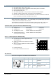
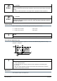
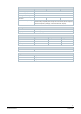
LED colors and patterns for SSA161.05 LED color Pattern Flashing interval Green Flashing 0.1 s Self-calibration 0.5 s Red Description Actuator stem is moving. Constant - Actuator stem reaches a set position. The LED turns off after it is constantly on for five seconds. Constant - Error* * Hint: calibration or power reset required. Type summary Type Stock number Operating voltage Running speed at 50 Hz Running time Control signal 2.5 mm Cable length SSA131.
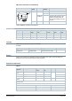
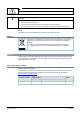
* Nominal volume flow at 0.5 mm stroke. Note: To ensure trouble-free operation of third-party valves with the SSA.. actuator, the valves must satisfy the following requirements: ● Threaded connections with coupling nut M30 × 1.5. ● Nominal force F ≤ 100 N ● Dimension X ≥ 8.3 mm ● Dimension Y ≤ 14.8 mm Controllers Type SSA131.00 SSA331.00 SSA161.05 AC 24 V AC 230 V AC/DC 24 V 3-position 3-position DC 0...10 V DXR2 DXR2..09T.., DXR2..10.., DXR2..11.., DXR2..12P.., DXR2..18.., DXR2..10PL..
CAUTION National safety regulations Failure to comply with national safety regulations may result in personal injury and property damage. ● Observe national provisions and comply with the appropriate safety regulations. Observe permissible temperatures (see "Technical data [➙ 8]"). The connecting cable of the actuator may come into contact with the hot valve body, provided the temperature of the valve body does not exceed 80 °C. Mounting WARNING ● ● Do not use pipe wrenches, spanners or similar tools.
CAUTION National safety regulations Failure to comply with national safety regulations may result in personal injury and property damage. ● Observe national provisions and comply with the appropriate safety regulations. CAUTION Phase cut and pulse-duration-modulated (PDM) signals are not suitable. Regulations and requirements to ensure the safety of people and property must be observed at all times! Commissioning When commissioning, check both wiring and functioning of the actuator.
WARNING Operating voltage must be switched off during any maintenance! NOTICE When carrying out service work on the plant, note the following: ● ● ● Switch off operating voltage. If necessary, disconnect electrical connections from the terminals. The actuator must be commissioned only with a correctly mounted valve in place! Repair The actuators cannot be repaired; the complete unit must be replaced.
Technical data Power supply Operating voltage Tolerance SSA131.00 SSA331.00 SSA161.05 AC 24 V ± 20 % AC 230 V ± 15 % AC 24 V ± 15 % Frequency Power consumption DC 24 V ± 20 % 50/60 Hz Running 0.8 VA 7 VA 2.5 VA Holding 0.2 VA 0.2 VA 2 VA Primary fuse or breaker rating External, 2 A quick blow Signal input SSA131.00 SSA331.00 SSA161.05 Control signal 3-position DC 0...10 V Input impedance for DC 0...10 V - 100 kOhm Parallel operation (number of actuators)1) Max. 24 1) Max.
Standards SSA131.00 SSA331.00 SSA161.05 II III EU conformity (CE) A5W00106106A RCM conformity A5W00106107A Housing protection degree IP 54 Protection class according to EN 60730 III Environmental compatibility The product environmental declaration (A5W00109220A) contains data on environmentally compatible product design and assessments (RoHS compliance, materials composition, packaging, environmental benefit, disposal).
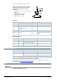
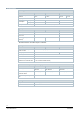
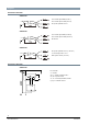
Diagrams Connection terminals SSA131.00 Y1 = Control signal OPEN (AC 24 V) Y2 = Control signal CLOSE (AC 24 V) G = System potential AC 24 V SSA331.00 Y1 = Control signal OPEN (AC 230 V) Y2 = Control signal CLOSE (AC 230 V) N = Neutral SSA161.05 G = System potential AC 24 V (+ DC 24 V) Y = Control signal DC 0...10 V G0 = System neutral (- DC 24 V) Connection diagrams SSA131.
SSA331.00 N = Controller Y = Actuator L = System potential AC 230 V N = System neutral Y1, Y2 = Control signal OPEN, CLOSE Q1, Q2 = Controller contacts SSA161.
Revision numbers Type Valid from rev. no. SSA131.00 ..A SSA331.00 ..A SSA161.05 ..A Issued by Beijing Siemens Cerberus Electronics Ltd. Smart Infrastructure No.1, Fengzhi East Road, Xibeiwang Haidian District, 100094 BEIJING, China Tel. +86 10 64768806 www.siemens.com/buildingtechnologies 12 Siemens Smart Infrastructure Document ID A6V11858276_en--_a Edition 2020-07-30 © Beijing Siemens Cerberus Electronics Ltd., 2020 Technical specifications and availability subject to change without notice.