
Data Sheet for Product
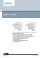
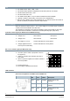
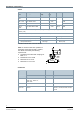
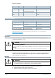
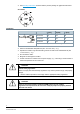
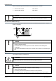

Table Of Contents

2
Siemens
A6V11858276_en
--
_e
Smart Infrastructure
2021
-
08
-
06
Use
● For radiator valves, VDN.., VEN.., VUN..
● For Siemens PICV (pressure independent combi valves) VPP46.. and VPI46..
● For MiniCombi valves VPD.., VPE..
● For small valves VD1..CLC
● For radiator valves (M30 × 1.5) from other manufacturers without adapter
● Typically in radiator, chilled ceiling, VAV and fan coil unit applications.
● Max. 24 units of SSA131.00, 6 units of SSA331.00 or 10 units of SSA161.05 are able to
operate in parallel, provided the controller output suffices.
Technical design
When the actuator is driven by DC 0…10 V control voltage or a 3-position signal, it produces
a stroke, which is transmitted to the valve stem.
The description of operation in this document applies to valve versions that are fully open
when valve stem is extended / no actuator is mounted (Normally Open (NO) valve).
3-position control signal (for SSA131.00 and SSA331.00 only)
● Voltage at Y1: Stem retracts Valve opens
● Voltage at Y2: Stem extends Valve closes
● No voltage at Y1 or Y2: Actuator maintains its current position
● Voltage applied to both Y1
and Y2 (not recommended):
Actuator maintains its current position
DC 0...10 V control signal (for SSA161.05 only)
● The valve opens / closes in proportion to the con-
trol signal at Y.
● At DC 0 V, actuator stem extended, the valve is
fully closed.
● When no power is supplied, the actuator maintains
its current position.
Y = Control signal Y [V]
H = Percentage of calibrated valve stroke
LED indication
LED colors and patterns for SSA131.00 and SSA331.00
LED Color Pattern Description
LED 1 Green Constant Actuator stem is fully
extended.
LED 2 Green Constant Actuator stem is moving in-
between.
LED 3 Green Constant Actuator stem is fully
retracted.