
Commissioning Instructions
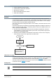
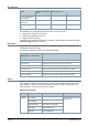
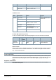
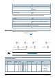
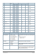
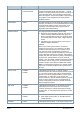
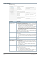
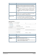
Table Of Contents

3
Siemens
A6V12066162_en
--
_b
Smart Infrastructure
2021
-
08
-
06
Self-calibration
Result
KNX button: Press button
> 20 s
KNX bus erase code =
02 07
All group object bindings
are reset/deleted
X X X
All parameters are reset to
default values
X X X
Individual addresses are
reset
X X
Self-calibration can be triggered by KNX command. It also occurs after:
● Applying bus voltage for the first time
● Downloading application each time
● Regular interval (180 days)
Two different self-calibration strategies are available in KNX S-Mode and displayed as Cali-
bration strategy parameters in ETS5.
Diagnostics
Diagnostics data is directly accessible as on-demand property by a tool or optionally via a
dedicated BA diagnostics object.
The actuator measures and stores the following information:
Object type = 352
Object instance = 1 Object index =
11
Description
RunTimeActr Indicates the open/close motor time [s] of the valve actuator
CumulRunRime Indicates the total motor power on time [s] of the actuator
CounterRePos Indicates the total number of valve repositioning events of the actuator
CounterDeviceJam Indicates how many times the valve was blocked by an obstacle
CounterPowerUp Indicates the total number of power up events of the actuator
CounterLowVoltage Indicates the total number of low voltage events of the actuator
Alarms
Alarms are defined to indicate abnormal behavior. There are two kinds of alarms in the actu-
ator: calibration and mechanical failure/jam. The stem position LED indicator turns to red if
either happens. If there is an alarm and the report function is enabled, the telegram of the
alarm information is sent at an interval of 15 minutes.
Mechanical failure/jam
Mode Description Define Telegram
S-Mode Log number 01 PID=51: AlarmInfo: 01 00
0A 03 0C 05
Alarm priority 00
Application area HAVC General =0A Hex
Error class Actuator fault = 03
Attributes
AlarmTextSupport +