Application program description Electromotoric actuator SSA118.09HKN With KNX communication for radiator valves, PICV and small valves ● ● ● ● ● ● ● A6V12066162_en--_b 2021-08-06 Support of KNX S-Mode (integration with ETS) Support of KNX PL-Link (integration with Desigo™ Room Automation) Direct mounting with coupling nut, no tools required Position and actuator motion indication (LED) Positioning force 100 N Parallel operation of multiple actuators possible Integral cable length 1.
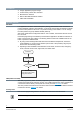
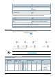
Introduction ● ● ● ● ● Usage: Application program usage Product family: HVAC valve actuators Manufacturer: Siemens Name: SSA KNX Networked Actuator ASN: SSA118.09HKN Function overview Workflow If no application has been downloaded (factory setting), the actuator enters construction mode immediately following self-calibration. In this mode, the actuator has limited functionality and the valve position is set to 25 % to prevent freezing of the radiator.
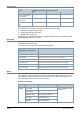
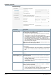
Self-calibration Result KNX button: Press button KNX bus erase code = > 20 s 02 07 All group object bindings are reset/deleted X X X All parameters are reset to default values X X X Individual addresses are reset X X Self-calibration can be triggered by KNX command.
Mode Description Define Telegram ErrorCodeSupport = 12 = 0C Alarm state InAlarm / Locked = 05 Calibration error Mode Description Define Telegram S-Mode Log number 02 Alarm priority Medium = 01 PID=51: AlarmInfo: 02 01 01 03 0C 05 Application area System & function of common interest = 01 dec = 01 hex Error class Actuator fault = 03 Attributes AlarmTextSupport + ErrorCodeSupport = 12 = 0C Alarm state InAlarm / Locked = 05 No alarm (HB repeat every 30 min) In case of no alarm indicatio
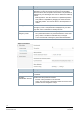
Device/tool Type Controllers and room units RDG.. RDG100KN, RDG160KN, RDG165KN, RDG200KN, RDG260KN Engineering and commissioning tools (partially suitable for device configuration) Tool for KNX S-Mode ETS5 The actuator works in PL-Link mode if the following controllers are connected: Device/tool Type Controllers DXR2 DXR2.M18, DXR2.E18, DXR2.M09, DXR2.E09 PXC3 PXC3.E75A Engineering and commissioning tools (partially suitable for device configuration) Tool for PL-Link ABT Site 4.1.
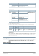
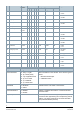
No. Name in ETS 2 Fault state Object function Transmit Flags Data point type KNX Range C R W T U ID DPT_Name Format 1 1 0 1 0 1.005 alarm 1 bit 0 = No alarm 1 = Alarm 3 Fault transmission Receive 1 0 1 0 1 1.003 enable 1 bit 0 = Disable 1 = Enable 4 Setpoint position Receive 1 0 1 0 1 5.001 scaling 1 byte 0...100 % 5 Forced position Receive 1 1 1 0 1 1.003 enable 1 bit 0 = Disable 1 = Enable 6 Actual position Transmit 1 1 0 1 0 5.
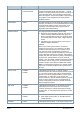
Objects Range Description Forced position 1 = Enter Force Mode 0 = Exit Force Mode If this object receives value “1”, the valve is driven to the position parametrized under "Forced mode" → "Actual position". The valve remains in this position until value “0” is sent from this object, thus cancelling "Forced mode". When this happens, the previous position is approached. This position is not changed even receiving another "Setpoint position". Actual position 0...
Objects Range Description 1 = True position specified by the local or remote override. Any "Setpoint position" is ignored until the override is complete, in which case this object receives value “0” and the actuator resumes normal operation. If the "Emergency mode" object was set to “1” before the local/remote override occurs, it is resumed once the override process is completed.
Parameter description Standard settings Parameters Description Hysteresis (COV) This function is not needed for normal operation. It is used mainly for diagnostics and troubleshooting. ● No COV, send when target position is reached: The current valve position is only sent after position adjustment. ● At change of x %: The current valve position is sent if different from the last sent value as of a value of x %. When the defined actuating value is reached, the valve position is sent as well.
Parameters Description Backup mode Defines the valve position when no "Setpoint position" ("Emergency mode") is received. As soon as a new actuating value is received, the new position is assumed. This parameter is displayed only if a value larger than 0 min is selected for “Backup timeout”. ● Backup position: The valve is driven to a predefined position. This position is adjustable by dragging the value bar below. ● Keep last position: The valve is driven to the last position received.
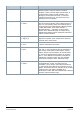
Parameters Description Cyclical transmission (Transmission of maximum position) Defines the time interval for sending the actuating value with object “Maximum position”. ● If there is more than one device (valve actuator or heating boiler) in a plant, option “No cyclical transmission” must be selected.
Valve characteristics Parameters Description Opening/closing direction Defines the operating mode of the installed valve and valve actuator. ● Normal (closed with pushed tappet): The valve closes when the actuator stem extends. Suitable for all common valves. ● Inverted (open with pushed tappet): The valve opens when the actuator stem extends. Designed for inverted valves. Method for additional pressing of rubber seal Defines how automatic adjustment is executed.
Parameters Description Minimum position Defines the minimum valve position the valve can reach. Behavior at minimum position underflow Defines which valve position is reached if the position/actuating value is lower than the defined minimum position. ● 0%: The valve actuator closes the valve completely. ● 0 % = 0 %, otherwise min. valve position: The valve actuator reaches the defined minimum position.
Condensation contact Parameters Description Cyclical transmission Defines if and how often the state of the connected condensation contact is sent. No cyclical transmission: Send only when the state changes. Every x min: The state is sent at intervals of x min. Minimum repetition time Defines the minimum interval for sending state changes. Upon frequent state changes, the parameter helps prevent bus traffic congestion.
Engineering and commissioning System environments NOTICE Good knowledge about KNX networks and tool operation (depending on the system environment) is required. To connect a PC with USB interface to a KNX network, an interface converter (e.g. OCI700, contained in OCI700.1) is required. Supported system/network environment and available engineering and commissioning tools are: System environment Engineering and commissioning tools KNX S-Mode ETS5 KNX PL-Link ABT Site 4.1.
KNX PL-Link commissioning When the device is connected to KNX PL-Link bus, conduct manual commissioning as follows: a) Connect ABT Site to the room automation station and activate the online commissioning function. b) Load Configuration page and select KNX PL-Link device. c) Configure SSA118.09HKN in this page. d) Download the configured project to room automation station. After download is completed, SSA118.09HKN restarts automatically.
Issued by Beijing Siemens Cerberus Electronics Ltd. Smart Infrastructure No.1, Fengzhi East Road, Xibeiwang Haidian District, 100094 BEIJING, China +86 10 64768806 www.siemens.com/buildingtechnologies Document ID A6V12066162_en--_b Edition 2021-08-06 © Beijing Siemens Cerberus Electronics Ltd., 2021 Technical specifications and availability subject to change without notice.