
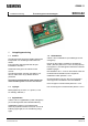
Installation Instructions


8/10
Siemens SE1G5996sv11
Smart Infrastructure 2020-02-10
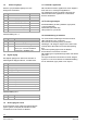
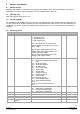
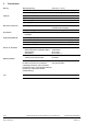
Addr
Function
Description
Initial
10 Left damper position 0 = unknown
1 = closed
2 = moving
3 = open
16 = damper alarm
32 = damper failure, failed to open
33 = damper failure, failed to close
R 0
11 Right damper position 0 = unknown
1 = closed
2 = moving
3 = open
16 = damper alarm
32 = damper failure, failed to open
33 = damper failure, failed to close
R 0
12 Left detector status 0 = disabled
1 = detector on
16 = detector service alarm
32 = detector fire alarm
48 = detector fire and service alarm
64 = detector in reset state
R 0 if detector is
disabled
otherwise
detector status
13 Right detector status 0 = disabled
1 = detector on
16 = detector service alarm
32 = detector fire alarm
48 = detector fire and service alarm
64 = detector in reset state
R 0 if detector is
disabled
otherwise
detector status
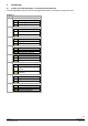
14 Reserved R Always 0
15 Temperature
measurement
Temperature in 0.1 degrees R
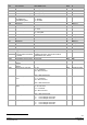
16 DIP status Settings 1 and Settings 2 DIP status
bit 0 = Settings 1 Dip 1
bit 1 Settings 1 Dip 2
….
Bit 7 Settings 1 Dip 8
R External state
17 Reserved R
18 Reserved R
19 Reserved R
20 External digital input
status
Inverterade
bit 0: DI1 status (0 = sluten)
bit 1: DI2 status (1 = öppen)
bit 2: DI3 status
bit 3: DI4 status
R External state
21 External digital output
state
0: off
1: on
R 0
22 Left detector B1
(0 .. 10V)
Voltage in mV R
23 Right detector B2
(0…10V)
Voltage in mV R
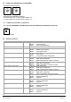
24 External control
This register is used to set
device status over
Modbus.
bit 0 external interlock
bit 1 external alarm. need to be rested with
reset alarms (Address 25)
…
R/W 0
25 Reset alarms bit 0 = 1 reset fire alarm
bit 1 = 2 reset external alarm
bit 2 = 4 reset Modbus alarm
bit 3 = 8 reset external alarm
R/W 0
26 Manual damper test 0 = no damper test
1 = Left damper test
2 = Right damper test
3 = Both dampers tested
R/W 0
..........
....