
Operating Instructions


6/16
Siemens Modbus för SOC7-128, slave mode SE1Z5996en7
Building Technologies 2 General 2015-08-26
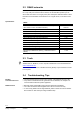
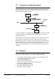
2.2 RS485 networks
RS485 is a balanced line, half-duplex transmission system that meets the requirements
for a truly multi-point communications network, and the standard specifies up to 32
drivers and 32 receivers on a single (2-wire) bus. Half-duplex data transmission means
that data can be transmitted in both directions on a signal carrier, but not at the same
time.
RS485
Mode of Operation Differential
Total Number of Drivers and Receivers on One Line (One
driver active at a time for RS485 networks)
32 Driver
32 Recvr
Maximum Cable Length 1200 meter
Maximum Data Rate (10m – 1200m) 10Mb/s-100Kb/s
Maximum Driver Output Voltage -7V to +12V
Driver Output Signal Level (Loaded Min.) +/-1.5V
Driver Output Signal Level (Unloaded Max) +/-6V
Driver Load Impedance (Ohms) 54
Max. Driver Current in High Z State, Power On +/-100uA
Max. Driver Current in High Z State, Power Off +/-100uA
Slew Rate (Max.) N/A
Receiver Input Voltage Range -7V to +12V
Receiver Input Sensitivity +/-200mV
Receiver Input Resistance (Ohms), (1 Standard Load for
RS485)
>=12k
2.3 Tools
Modbus slave devices can be tested with several Modbus master simulation tools, like
“Modbus Poll” or “ModScan”, from a computer. Modbus Poll can be downloaded from
www.modbustools.com
.
A RS485/RS232 converter or a Modbus RTU/TCP gateway may be needed to connect
to a computer.
2.4 Troubleshooting, Tips
The slave address must be unique in the network, valid addresses are from1-247.
Only reference addresses that are generated can be read/write, see chapter 5 for
more information about the specific application.
Baudrate, Parity and Stopbits must match the network and the Master.
The 2-wire bus is NOT interchangeable and must be connected correctly.
In case of long distance and/or high Baudrate, please consider end of line resistors
like 120 Ohm on both sides (according to RS485 rules).
Specifications
Modbus
Communication error
RS485 network