SOC7-128 Modbus for SOC7-128, slave mode General Engineering Guide SE1Z5996en7 2015-08-26 Building Technologies
/16 Siemens Building Technologies Modbus för SOC7-128, slave mode SE1Z5996en7 2015-08-26
Contents 1 About this Document .................................................................................... 4 1.1 Foreword ....................................................................................................... 4 1.2 Notes on Use ................................................................................................ 4 1.3 Symbols and Abbreviations .......................................................................... 4 2 General .................................
1 About this Document 1.1 Foreword The purpose of this document is to provide users with a quick and simple means to familiarize themselves with the configuration and use of Modbus on the firedamper control system SOC7-128. Purpose 1.2 Target audience Notes on Use This document is intended for integrators who perform commissioning of the Modbus communication.
2 General 2.1 The Modbus protocol The following section provides only a brief overview of the Modbus protocol. For the full specification, refer to "Modicon Modbus Protocol Reference Guide PI-MBUS-300 Rev. J". Master/slave protocol The Modbus is a master/slave protocol. By definition, this means that a Modbus network contains one, and only one, master and at least one slave. Transactions on the Modbus The Modbus master starts the transactions on the network with a slave query.
2.2 RS485 networks RS485 is a balanced line, half-duplex transmission system that meets the requirements for a truly multi-point communications network, and the standard specifies up to 32 drivers and 32 receivers on a single (2-wire) bus. Half-duplex data transmission means that data can be transmitted in both directions on a signal carrier, but not at the same time.
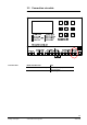
3 Connection and Configuration 3.1 The system The SOC7 is a system for monitoring and surveillance of fire dampers and smoke detectors. The system consist of the control unit SOC7-128, the multibox SOC7-M2 and the relay unit SOC7-R1. The control unit can handle up to 64 multiboxes and each multibox can handle 2 dampers and smoke detectors. The relay unit has one relay for interlocking of the supply fan. The system can be divided in up to 10 fire groups.
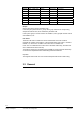
Multibox 1 2 3 4 5 6 7 8 Ahu, (relay unit) 1 1 2 2 3 3 4 4 Group A A B B C C D D User zones 1 1 1 2 3 3 3 3 Comment Office hour 07:00 – 17:00 Office hour 08:00 – 20:00 Office hour 07:00 – 18:00 Groups: Groups refers to the groups in the SOC7-128. In the example system there are 4 groups. Each group interlocks its corresponding dampers and also its ahu, this is controlled by the SOC7-128. In this system group A consists of Ahu1 and multibox 1,2 and group B consists of Ahu2 and multibox 3,4 etc.
3.3 Connection via cable Follow the instructions below to connect to the RS485 interface.
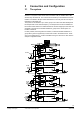
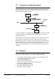
3.4 Connection via ethernet network To connect to the system unit SOC7-128 via a Ethernet network a gateway must be used at the SOC7-128. If the master cannot integrate Modbus/TCP a gateway must also be installed at that side. The picture bellows shows a topology where a gateway has been installed also at the master side. For correct configuration of the gateways, please refer to the specific gateway manuals.
4 Register map and function codes 4.1 Register map Modbus registers are organized into reference types identified by the leading number of the reference address: The "x" following the leading character represents a four-digit reference address. Modbus Data formats ModbusType Reference Description (refer to a Master device) Coil Status 0xxxx Read/Write Discrete Outputs or Coils. A 0x reference address is used to drive output data to a digital 1-bit output channel.
5 Reference addresses 5.1 General This chapter describes the reference addresses used in the application. Used addresses Reference addresses marked “Not used” are should not be accessed. (SOC7-128 will answer with the correct error message.) Do not Read/Write any addresses not mentioned in this manual. If so there will be an exception response and the communication fails.
5.4 Input Register Address 3x0001 3x0002 Description Copy of discrete inputs 4..1 in least significant bit Bit representation: 00=Fire alarm if set 01=service alarm if set 02=External alarm if set 03=Interlock if set 04..15=Not used, read as 0(zero) Actual test interval, days 0..7, 0 for disabled. If 7 days, (weekday *8) is added (Sun 0, Mon 8, Tue 16, Wed 24, Thu 32, Fri 40, Sat 48) Values / Unit Bit Remark Value 0..
Address 3x0301..310 3x0311..400 3x0401..499 3x0500 3x0501..510 5.5 Description Fan status for group A-J Bit: 00=On, fan is on if set 01=Active if set 02=Enabled if set 03=Interlock if set Not used Interlock status for multibox Bit 00=Multibox interlock if set 01=Keep fan running during interlock if set Not used Interlock status for group A-J Bit 00=Group interlock if set Values / Unit Bit Bit This information can also be read on address 3x0101..
Index A Abbreviations .............................................................. 4 About this document ................................................... 4 C Configuration ............................................................... 7 Configure .................................................................. 10 Connect ....................................................................... 9 Connection .................................................................. 7 F Function codes...........
Siemens AB Infrastructure & Cities Sector Siemens Building Technologies Elektronvägen 4 141 87 Huddinge, Sweden Tel. +46 8-578 410 00 Fax +46 8-578 419 99 http://www.siemens.