
Product Overview


Document Number: 129-217
Installation Instructions
September 30, 2002
Siemens Building Technologies, Inc. Page 3 of 6
Wiring
CAUTION:
Use care when removing the knockout. Do not
damage the circuit board.
Do not use autotransformers. Use earth ground
isolating step-down Class 2 transformers.
Determine supply transformer rating by summing total
VA of all actuators used. The maximum rating for a
Class 2 power supply circuit is 100 VA.
Actuator Power
Consumption
Actuators Per
Class 2 Supply Circuit*
(80% of Transformer VA)
SKD62U 17 VA 4
SKD82.50U 10 VA 8
SKD82.51U 15 VA 5
* Operating more actuators requires additional
transformers or separate 100 VA power supplies.
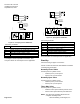
Wiring Diagrams
SKD62U Figures 9 and 10
SKD82.50U/51U Figures 11 through 13
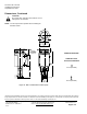
SKD62U
Calib.
Status
DIPSwitches
FunctionsSeeBelow
LEDStatus
Indication
StrokeCalibration
Connection
Terminals
EA1068R1
G0
AC24V
50/60Hz 0...10V
4...20mA
G
G0
Chm
GYMUZ
OK
Green
Status
Calib.
Red
Calib.
Error
Valve
Jam
1 2
Figure 9. SKD62U.
DIP
Switches
1
Selection of
Control Signal
2
Selection of Flow
Characteristic
ON 4 to 20 mA Modified*
OFF
(Factory Setting)
0 to 10 Vdc Default
*Changing the default setting will modify an equal
percentage valve to a linear flow characteristic
. When set to
default, the flow characteristic is determined by the valve
body.
GB1M
G0
Y1
GM
Z
G0
Y
U
BM
G(SP)
F1
Y1
N1
B1
G0(SN)
32
1
M
Sensor
TemperatureLimiter
Controller
Actuator
B1
F1
N1
Y1
AC24V
EA1074R1
Figure 10.
Connecting Terminals
24 Vac
G System Potential (SP)
G0 System Neutral (SN)
Y Control Input: 0 to 10 Vdc or 4 to 20 mA
(DIP switch selectable)
Z Override Control
(See Technical Instructions 155-180P25)
M Measuring Neutral
U Output for 0 to 10 Vdc or 4 to 20 mA
measuring voltage. It will match the input
signal type.
The position output signal U will switch from 0 to 10
Vdc to 4 to 20 mA when a 4 to 20 mA input signal is
selected and used on the terminal
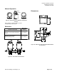
Wiring for SKD82…U
EA0394R2
G
Y1
Y2
21
Figure 11. Location of Terminals.